Part 4 - Integer Arithmetic and Memory Access
Integer arithmetic. Moving data to and from memory.
Integer Addition and Subtraction Instructions
This chapter discusses the MIPS instructions for performing 32-bit integer addition and subtraction. Some topics of integer representation with bit patterns are reviewed.
Chapter Topics:
- Overflow in unsigned binary and two's complement (review).
- The
addandadduinstructions. - Sign extention.
- The
addiandaddiuinstructions. - The
subandsubuinstructions. - Using
addito load a register with a negative integer.
Question 1
Say that a processor has a full set of bit manipulation instructions. Can it do arithmetic with these instructions?
Answer
Yes. (And it can do floating point arithmetic as well).
Arithmetic as bit manipulation
Integers are represented with bit patterns, so integer operations are bit manipulation operations. Some very small, very fast processors provide no data manipulation instructions other than bit pattern manipulation. Adding two integers is done by implementing the Binary Addition Algorithm (see Chapter 8) with these bit instructions.
Luckily, MIPS has instructions that perform integer arithmetic. The normal size of an integer is 32 bits (the same as the size of a register). Longer or shorter integer arithmetic is done using bit manipulation instructions in combination with 32-bit arithmetic instructions.
Question 2
The MIPS addu instruction performs the Binary Addition Algorithm on two 32-bit patterns. What integer representation method can be used with it?
- Unsigned Binary?
- Two's Complement?
- Both?
Answer
Both
Binary addition algorithm
The Binary Addition Algorithm works for both methods of integer representation. The same MIPS instruction (addu) is used for both methods. However, the overflow condition is different for each method.
Binary Addition Algorithm: detecting overflow:
| Unsigned binary | Two's complement |
|---|---|
| The result is correct if the carry out of the high order column is zero. | The result is correct if the carry into the high order column is the same as the carry out of the high order column. The carry bits can both be zero or both be one. |
Question 3
Use the Binary Addition Algorithm on these 8-bit patterns:
 1010 1011
 0101 0101
———————————
Does overflow happen for:
- Unsigned Binary?
- Two's Complement?
Answer
11111 111
 1010 1011
 0101 0101
———————————
 0000 0000
Does overflow happen for:
- Unsigned Binary? Overflow -- The carry out is one.
- Two's Complement? In Range -- The carry in is the same as the carry out.
The addu instruction
The addu instruction performs the Binary Addition Algorithm on the contents of two 32-bit registers and places the result in the destination register. The destination register can be the same as one of the source registers. The addu instruction mechanically grinds through the Binary Addition Algorithm, producing a 32-bit result from two 32-bit operands. Overflow is ignored (that is what the "u" at then end of the mnemonic means).
addu  d,s,t        # d <—— s + t
                   # no overflow trap
There is another instruction, add, which causes a trap when two's complement overflow is detected. Other than that, it is the same as addu. A trap is an interruption in the normal machine cycle. Typically on a computer system a trap results in sending control back to the operating system.
add   d,s,t        # d <—— s + t
                   # with overflow trap
Most assembly programmers deal with overflow by making sure that the operands won't cause it. Usually they use the addu instruction. Until you know how to handle a trap that is the approach we will take.
Question 4
What is the range of integers that can be represented with 32-bit two's complement?
-2— to +2—-1(Pick an exponent for each "2").
Answer
-231 to +231-1(There are bit patterns. Half of them are for negative integers, and the remaining are for the positive integers and zero).
Example program
Here is the previous addition problem extended to 32 bits.
carry:   0 0000 0000 0000 0000 0000 0001 1111 111
           0000 0000 0000 0000 0000 0000 1010 1011         000000AB
           0000 0000 0000 0000 0000 0000 0101 0101         00000055
           ---------------------------------------         --------
           0000 0000 0000 0000 0000 0001 0000 0000         00000100
What was unsigned overflow with 8-bit unsigned arithmetic is within range for 32-bit arithmetic.
## AddSome.asm
##
## Program to demonstrate addition
        .text
        .globl  main

main:
        ori      $8, $0, 0xAB       # put 0x000000AB into $8
        ori      $9, $0, 0x55       # put 0x00000055 into $9
        addu     $10,$9, $8         # $10 <—— sum

## End of file
Question 5
Are registers $9 and $8 changed by the addu instruction in this program?
Answer
No. Operand registers are not changed, unless one is also the destination register.
Run of the program
Here is a run of the program. The results are as expected. The source code is shown at the right of the text section. In the middle column of the text section the decimal equivalents of the immediate operands is shown in the instructions.
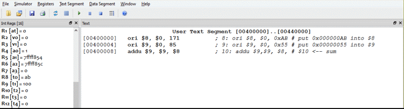
To express an immediate operand using decimal notation omit the leading 0x. The following puts the same bit pattern in the registers as the previous assembly language:
        ori      $8, $0, 171       # put 171 into $8 (this is 0xAB)
        ori      $9, $0,  85       # put  85 into $9 (this is 0x55)
        addu     $10,$9,  $8       # $10 <—— sum
Of course, the immediate operand in the machine instruction is a 16-bit pattern. The assembler allows you to specify this pattern using the hexadecimal pattern name, or a decimal integer that is converted into a 16 bit pattern.
Expressed in hex, the program computed 0xAB + 0x55 = 0x100
Expressed in decimal, the program computed 171 + 85 = 256
Question 6
(Review:) Can a negative const be used with the instruction:
ori $d,$0,const
Answer
No. const is a 16-bit immediate operand that is zero-extended to a 32-bit integer when it is copied to $d. So it can't be negative.
Negating a two's complement integer
Here is an interesting bit manipulation problem. Say that we wish to negate the representation of an integer that has been loaded into a register. Later in these pages there is an easy way to negate an integer, but for now let us use the instructions you already have seen.
Recall that a two's complement integer is made negative by reflecting the bits then adding one.
Question 7
Say that register $8 has been loaded with +82 by using:
ori $8,$0,82
What instructions can do the following:
- Reflect the bits in
$8 - Add one to
$8
Answer
Reflect the bits in
$8:nor $8,$8,$0
Add one to
$8:ori $9,$0,1
addu $8,$8,$9
Example program
Here is a program that does that. There are much better ways to load a register with a negative integer. However, this is a nice example of bit manipulation.
## handMadeNeg.asm
##
## Program to demonstrate two's complement negative
##
## The program adds +146 to -82, leaving the result in $10

        .text
        .globl  main

main:
        ori      $7, $0, 146        # put +146 into $7
        ori      $8, $0,  82        # put 82 into $8
        nor      $8, $8,  $0        # reflect
        ori      $9, $0,   1        #
        addu     $8, $8,  $9        # add 1: $8 = -82
        addu    $10, $7,  $8        # (+146) + (-82)

## End of file
Question 8
146 - 82 = _____?
In hex = _____?
Answer
146 - 82 = 64
In hex = 0x40
Sign extension
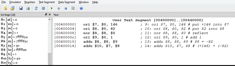
A run of the program produces the expected result.
So that one could be added to register $8, the one was first loaded into another register. It would be nice if there were an "add one" instruction. Many processors have such an instruction.
MIPS has an "add immediate unsigned" instruction: addiu d,s,const. It can be used to add one to register $8 like this:
addiu $8,$8,1
The immediate operand of this instruction is 16 bits (as are all MIPS immediate operands). However, when extended to a 32-bit operand by the ALU it is sign extended: The value of the left-most bit of the immediate operand (bit 15) is copied to all bits to the left (into the high-order bits). So if the 16-bit immediate operand is a 16-bit two's complement negative integer, the 32-bit ALU operand is a 32-bit version of the same negative integer. The left-most bit of a two's complement integer is sometimes called the "sign bit".
Question 9
Here is a 16-bit two's complement negative one:
1111 1111 1111 1111
Sign-extend it to 32 bits:
Here is a 16-bit two's complement negative one written in hex:
FFFF
Write a 32-bit negative one in hex:
Answer
A 16-bit two's complement negative one:
FF FF = 1111 1111 1111 1111
Sign-extended:
FF FF FF FF = 1111 1111 1111 1111 1111 1111 1111 1111
The sign-extended version is a 32-bit negative one.
The fond addiu instruction
The addiu instruction includes a 16-bit immediate operand. When the ALU executes the instruction, the immediate operand is sign-extended to 32 bits. If two's complement overflow occurs during the addition, it is ignored.
addiu   d,s,const        # d <—— s + const.
                         # Const is 16-bit two's comp. sign-extended to 32 bits
                         # when the addition is done. No overflow trap.
There is also an add immediate instruction that does trap if overflow is detected during addition. We won't use it:
addi    d,s,const        # d <—— s + const.
                         # Const is 16-bit two's comp. sign-extended to 32 bits
                         # when the addition is done. Overflow trap.
Question 10
Here is the previous program, that added +146 with -82. Rewrite it using the addiu instruction. Put the result in $10.
    ori      $7, $0, 146        # put +146 into $7
    ori      $8, $0,  82        # put 82 into $8
    nor      $8, $8,  $0        # reflect
    ori      $9, $9,   1        #
    addu     $8, $8,  $9        # add 1: $8 = -82
    addu    $10, $7,  $8        # (+146) + (-82)
Answer
    ori      $7, $0, 146        # put +146 into $7
    addiu    $10,$7,-82         # add -82
The program is much shorter.
The subu instruction
MIPS has two integer subtraction instructions:
subu   d,s,t        # d <—— s - t .
                    # No overflow trap.
                    # This is equivalent to $d <—— s + (-t)
                    # where (-t) is reflect-add-one of t.

sub    d,s,t        # d <—— s - t .
                    # Overflow is trapped!
                    # This is equivalent to $d <—— s + (-t)
                    # where (-t) is reflect-add-one of t.
Question 11
When ori $d,$0,const is used to load the register $d, const is 16-bit unsigned binary. Say that you want to load $8 with a negative 86. Will the following work?
addiu $8,$0,-86 # $8 <—— -86
Answer
Yes. The immediate operand -86 is sign-extended to 32 bits then added to a 32-bit zero. The sum (-86) is loaded into $8.
The absent subtract immediate
You would expect that since there are add, addu, addi, addiu and since there are sub, subu that there would be subtract immediate instructions. But there are not. The add immediate instruction is used. To subtract 201 from register $10 using an immediate operand, do this:
addiu $8,$10,-201 # $8 <—— $10 - 201
Say that we want to compute 5 * x - 74 where the value x is in register $8. MIPS has an integer multiply instruction, but let us say that we don't want to use it. How can 5 * x be done using the instructions you have seen so far?
Question 12
How could you compute 4 * $8 + $8?
Answer
Multiply $8 by four by shifting left two positions, then add it the original $8.
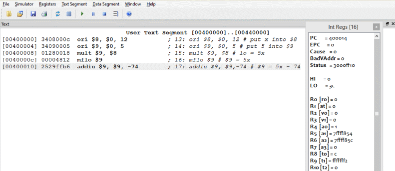
Example program
Here is the program. Unfortunately, there are a few blanks. This would be a good time to use that scratch pad and pencil next to your keyboard.
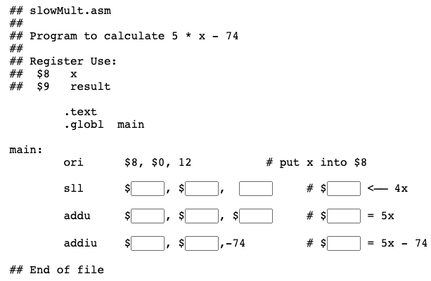
Question 13
Fill in the blanks to finish the program. The final result should be in register $9.
Answer
The complete program is below.
Filled blanks
## slowMult.asm
##
## Program to calculate 5 * x - 74
##
## Register Use:
##  $8   x
##  $9   result

        .text
        .globl  main

main:
        ori      $8, $0, 12        # put x into $8
        sll      $9, $8,  2        # $9 = 4x
        addu     $9, $9, $8        # $9 = 5x
        addiu    $9, $9,-74        # $9 = 5x - 74

## End of file
Question 14
Could the program be written using just one register?
Answer
No, because the original value x is used several times and needs to be held in a register.
(The program could be written with one register if you could use main memory to store x. But these notes have not told you how, yet).
Chapter quiz
Instructions: For each question, choose the single best answer. Make your choice by clicking on its button. You can change your answers at any time. When the quiz is graded, the correct answers will appear in the box after each question.
Question 1
How many bits are the operands of the ALU?
- (A) Always 32.
- (B) 8, 16, or 32
- (C) 32 or 64
- (D) Any number of bits up to 32.
Answer
A
Question 2
What procedure does the addu instruction call for?
- (A) The binary addition algorithm.
- (B) The unsigned addition algorithm.
- (C) The bit-wise addition algorithm.
- (D) The universal addition algorithm.
Answer
A
Question 3
What type of data may be in the registers used as operands for the addu instruction?
- (A) 32-bit unsigned in both registers.
- (B) 32-bit two's complement in both registers.
- (C) 32-bit unsigned or 32-bit two's complement, the same type in each register.
- (D) 32-bit unsigned or 32-bit two's complement, either type in either register.
Answer
C
Question 4
What is a trap?
- (A) A trap is an interruption in the normal machine cycle.
- (B) A trap is an instruction that captures data.
- (C) A trap is a shortened version of a normal 32-bit instruction.
- (D) A trap is a bus signal that says that something is wrong.
Answer
A
Question 5
Write the instruction that adds the contents of registers $8 and $9 and puts the result in register $13.
- (A) add $8,$9,$13
- (B) addi $8,$9,$13
- (C) addu $13,$8,$9
- (D) add $9,$8,$13
Answer
C
Question 6
Can the immediate operand of an addiu instruction be a two's complement negative integer?
- (A) No. The immediate operand is zero-extended to 32 bits.
- (B) Yes. When the instruction is executed, the immediate operand is sign-extended to 32 bits.
- (C) No. A 16-bit immediate operand is too small for two's complement.
- (D) Yes. Immediate operands are always two's complement.
Answer
B
Question 7
What is it called when bit 15 of a 16-bit immediate operand is copied to the 16 bits to its left to form a 32-bit operand?
- (A) Sign extention
- (B) Bit extention
- (C) Zero extention
- (D) Immediate extention
Answer
A
Question 8
Write an instruction that adds the value 12 to the value in register $6. Use an instruction which ignores overflow.
- (A) add $6,12
- (B) addi $6,$0,12
- (C) addiu $6,$6,12
- (D) addi $6,12
Answer
C
Question 9
What integer subtraction instruction uses two operand registers, one result register, and does not trap if overflow is detected?
- (A) subu
- (B) sub
- (C) subi
- (D) subiu
Answer
A
Question 10
Which instruction loads register $17 with a -99?
- (A)
addiu $17,$0,-99 - (B)
sub $17,$0,-99 - (C)
addiu $17,-99 - (D)
subu $17,$17,99
Answer
A
Programming exercises
For these programming exercises, use only those instructions that have been discussed so far in these notes:
add | sll |
addi | srl |
addiu | sub |
addu | subu |
and | nor |
andi | xor |
or | xori |
ori |
In the Settings menu of SPIM set Bare Machine ON, Allow Pseudo Instructions OFF, Load Trap File OFF, Delayed Branches ON, Delayed Loads ON, Mapped IO OFF, Quiet OFF.
Run the programs by setting the value of the PC to 0x400000 and then single stepping (pushing F10) or by multiple stepping (push F11 and enter a number of steps). Observing the results in the SPIM window.
Exercise 1 (*) - column addition
Write a program that adds up the following integers:
 456
-229
 325
-552
Leave the answer in register $8.
Exercise 2 (*) - shifting and adding
Initialize the sum in register $8 to zero. Then add 409610 to $8 sixteen times. You don't know how to loop, yet, so do this by making 16 copies of the same instruction. The value 409610 is 0x1000.
Next initialize register $9 to 409610. Shift $9 left by the correct number of positions so that registers $8 and $9 contain the same bit pattern.
Finally, initialize aregister $10 to 409610. Add $10 to itself the correct number of times so that it contains the same bit pattern as the other two registers.
Exercise 3 (*) - trapping overflow
Initialize register $9 to 0x7000. Shift the bit pattern so that $9 contains 0x70000000. Now use addu to add $9 to itself. Is the result correct?
Now use the add instruction and run the program again. What happens?
This may be the only time in this course that you will use the add instruction.
Exercise 4 (*) - arithmetic expressions
Let register $8 be x and register $9 be y. Write a program to evaluate:
3x - 5y
Leave the result in register $10. Inspect the register after running the program to check that the program works. Run the program several times, initialize x and y to different values for each run.
Exercise 5 (**) - two's complement
Let register $8 be x. Write a program that computes 13x. Leave the result in register $10. Initialize x to 1 for debugging. Then try some other positive values.
Extend your program so that it also computes -13x and leaves the result in register $11 (This will take one additional instruction.) Now initialize x to -1. Look at your result for 13x. Is it correct?
Integer Multiplication, Division, and Arithmetic Shift
This chapter discusses the MIPS instructions for performing 32-bit integer multiplication. Some topics of integer representation with bit patterns are reviewed.
Chapter Topics:
- Integer multiplication and division
- The hi and lo registers
- The
multandmultuinstructions - The
divanddivuinstructions - The
mfhiandmfloinstructions - Arithmetic shift right
- The
sraInstruction
Question 1
Multiply 99_10 times 99_10: ________
How many decimal places does each operand (99) take: ________
How many decimal places does the result take: ________
Answer
Multiply 99_10 times 99_10: 9801
How many decimal places does each operand (99) take: 2
How many decimal places does the result take: 4
Twice the number of places
        10110111            B7          183
        10100010            A2          162
        ————————            ——          ———
        00000000           16E          366
       10110111.          726         1098
      00000000..                      183
     00000000...
    00000000....
   10110111.....
  00000000......
 10110111.......
————————————————          ————        —————
 111001111001110          73CE        29646
The product of two N-place decimal integers may need 2N places. This is true for numbers expressed in any base. In particular, the product of two integers expressed with N-bit binary may need 2N bits. For example, in the picture, two 8-bit unsigned integers are multiplied using the usual paper-and-pencil multiplication algorithm (but using binary arithmetic).
The two 8-bit operands result in a 15-bit product. Also shown is the same product done with base 16 and base 10 notation.
Question 2
Is a 32-bit general register always able to hold the result of multiplying two 32-bit integers?
Answer
No. In general, 64 bits are needed.
MIPS multiply unit

MIPS contains two 32-bit registers called hi and lo. These are not general purpose registers. When two 32-bit operands are multiplied, hi and lo hold the 64 bits of the result. Bits 32 through 63 are in hi and bits 0 through 31 are in lo.
Here are the instructions that do this. The operands are contained in general-purpose registers.
mult    s,t        # hilo <— $s * $t   (two's comp operands)
multu   s,t        # hilo <— $s * $t   (unsigned operands)
There is a multiply instruction for unsigned operands, and a multiply instruction for signed operands (two's complement operands). Integer multiplication never causes a trap.
Confusion Alert! with add and addu, both perform the same operation. The "u" means "don't trap overflow". With mult and multu, different operations are carried out. Neither instruction ever causes a trap.
If the operands are too big, overflow will happen. But with these instructions the overflow will not cause a trap.
Question 3
Two small integers are multiplied. Where is the result?
Answer
If the result is small enough all the significant bits will be contained in lo, and hi will contain all zeros.
Significant bits
The significant bits in a positive or unsigned number represented in binary are the most significant 1 bit (the leftmost 1 bit) and all bits to the right of it. For example, the following has 23 significant bits:
0000 0000 0100 0011 0101 0110 1101 1110
We will mostly write programs that keep the result under 32 bits in length. When this is true, the result of a multiplication will be in lo.
The significant bits in a negative number represented in two's complement are the most significant 0 bit (the leftmost 0 bit) and all bits to the right of it. For example, the following has 23 significant bits:
1111 1111 1011 1100 1010 1001 0010 0010
To ensure that a product has no more than 32 significant bits, ensure that the sum of the number of significant bits in each operand is 32 or less. For the programming in this course you will not need to be careful about this.
Question 4
About how many significant bits do you expect in this product:
01001010 × 00010101
Answer
About 12 significant bits.
The mfhi and mflo instructions
Two instructions move the result of a multiplication into a general purpose register:
mfhi    d        #  d <— hi.  Move From Hi
mflo    d        #  d <— lo.  Move From Lo
The hi and lo registers cannot be used with any of the other arithmetic or logic instructions. If you want to do something with a product, it must first be moved to a general purpose register.
However there is a further complication on MIPS hardware:
Rule: Do not use a multiply or a divide instruction within two instructions after mflo or mfhi. The reason for this involves the way the MIPS pipeline works.
On the SPIM simulator this rule does not matter (but on actual hardware it does.)
Question 5
Must you move the result of one multiply from lo and hi before you start another multiply operation?
Answer
Yes.
Example program
This program evaluates the formula 5*x - 74 where the value x is in register $8. Assume that x is two's complement.
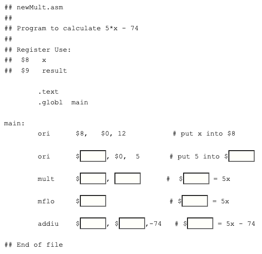
Question 6
Fill in the blanks. You may wish to copy the program into your text editor and make the changes there. Then you can test your answers by saving the file and running the program with SPIM.
Answer
The answer is below.
Completed program
Here is the completed program. Only two registers are needed. Register $9 is used to accumulate the result in several steps.
## newMult.asm
##
## Program to calculate 5*x - 74
##
## Register Use:
##  $8   x
##  $9   result

        .text
        .globl  main

main:
        ori      $8, $0, 12       # put x into $8
        ori      $9, $0,  5       # put 5 into $9
        mult     $9, $8           # lo = 5x
        mflo     $9               # $9 = 5x
        addiu    $9, $9,-74       # $9 = 5x - 74

## End of file
Question 7
What does the u mean in each of the following instructions:
addu:____________________multu:____________________
Answer
addu: Do not trap on overflow.multu: Operands are unsigned.
A run of the program
The mult instruction assumes two's complement operands. Run the program by initializing the PC to 0x400000 and then pushing F10 (single step) five times.
The result is as expected.
5 × 12 - 74 = -14 = 0xFFFFFFF2
The product 5 × 12 = 60_ten = 0x3C remains in lo.
Question 8
Use integer division (in base ten) to calculate the quotient and remainder of:
99 /  2   =    _______ Remainder ______

99 / 50   =    _______ Remainder ______
Answer
99 / 2   =  49 R 1
99 / 50  =   1 R 49
The div and divu instructions

With N-digit integer division there are two results, an N-digit quotient and an N-digit remainder. With 32-bit operands there will be (in general) two 32-bit results. MIPS uses the hi and lo registers for the results:
Here are the MIPS instructions for integer divide. The "u" means operands and results are in unsigned binary.
div    s,t        #  lo <— s div t
                  #  hi <— s mod t
                  #  operands are two's complement
divu   s,t        #  lo <— s div t
                  #  hi <— s mod t
                  #  operands are unsigned
Question 9
(Review:) What instruction would be used to move the quotient into register $8?
Answer
mflo $8
The instructions mflo and mfhi are used to get the results of an integer divide.
Example program
For this example say that we wish to calculate (y + x) / (y - x). The argument x is in $8; y is in $9. The quotient is to be placed in $10 and the remainder in $11. Assume two's complement integers. Here is the program. Sadly, it has some holes:
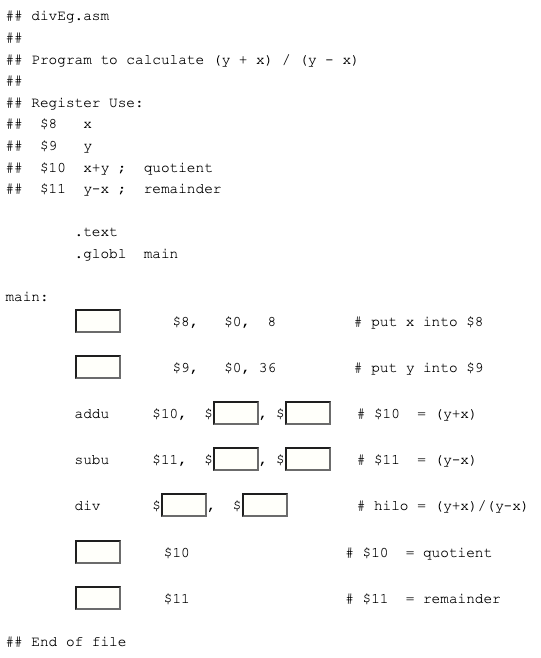
Question 10
Fill in the holes.
Answer
See below.
Filled holes
Here is the complete program:
## divEg.asm
##
## Program to calculate (y + x) / (y - x)
##
## Register Use:
##  $8   x
##  $9   y
##  $10  y+x
##  $11  y-x

        .text
        .globl  main

main:
        ori      $8,   $0,  8         # put x into $8
        ori      $9,   $0, 36         # put y into $9
        addu     $10,  $9, $8         # $10  = (y+x)
        subu     $11,  $9, $8         # $11  = (y-x)
        div      $10,  $11            # hilo = (y+x)/(y-x)
        mflo     $10                  # $10  = quotient
        mfhi     $11                  # $11  = remainder

## End of file
Question 11
(36+8) / (36-8) = _____ Remainder _____
Answer
(36+8) / (36-8) = 1 Remainder 16, or 0x1 Remainder 0x10
A run of the program
Here is an example run of the program:
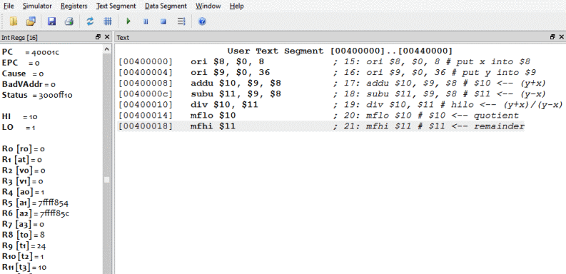
As usual, a stunning success.
Question 12
Here is the 16-bit two's complement representation for -16.
1111 1111 1111 0000
Perform a logical shift right by two positions. Is the resulting pattern the correct representation for -16/4?
Answer
1111 1111 1111 0000 → 0011 1111 1111 1100
Is the resulting pattern the correct representation for -16/4? No. The result represents a large positive number, not -4.
Shift right arithmetic
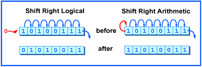
A right shift logical can not be used to divide a negative integer by two. The problem is that a shift right logical moves zeros into the high order bit. This is desirable in some situations, but not for dividing negative integers where the high order bit is the "sign bit." An arithmetic right shift replicates the sign bit as needed to fill bit positions.
Question 13
Is there a need for an arithmetic shift left instruction?
Answer
No. A logical shift left moves zeros into the low-order bit, which is correct for both signed and unsigned integers.
The sra instruction
MIPS has a shift right arithmetic instruction:
sra    d,s,shft   #  $d <— s shifted right
                  #  shft bit positions.
                  #  0 ≤ shft ≤ 31
Sometimes you need to divide by two. This instruction is faster and more convenient than the div instruction.
Question 14
Does the sra instruction give the correct results for unsigned integers?
Answer
No. For unsigned integers the "sign bit" should not be replicated.
Chapter quiz
Instructions: For each question, choose the single best answer. Make your choice by clicking on its button. You can change your answers at any time. When the quiz is graded, the correct answers will appear in the box after each question.
Question 1
If you have two integers, each represented in 32 bits, how many bits might be needed to hold the product?
- (A) 16
- (B) 32
- (C) 64
- (D) 128
Answer
C
Question 2
What are the names of the two registers that hold the result of a multiply operation?
- (A) high and low
- (B) hi and lo
- (C) R0 and R1
- (D) $0 and $1
Answer
B
Question 3
Which operation is used to multiply two's complement integers?
- (A) mult
- (B) multu
- (C) multi
- (D) mutt
Answer
A
Question 4
Which instruction moves the least significant bits of a product into register eight?
- (A) move $8,lo
- (B) mvlo $8,lo
- (C) mflo $8
- (D) addu $8,$0,lo
Answer
C
Question 5
If you have two integers, each represented in 32 bits, how many bits should you be prepared to have in the quotient?
- (A) 16
- (B) 32
- (C) 64
- (D) 128
Answer
B
Question 6
After a div instruction, which register holds the quotient?
- (A) lo
- (B) hi
- (C) high
- (D) $2
Answer
A
Question 7
What instruction is used to divide two's complement integers?
- (A) dv
- (B) divide
- (C) divu
- (D) div
Answer
D
Question 8
Perform an arithmetic shift right by two bits of the following bit pattern:
- (A) 1110 0110
- (B) 0010 0110
- (C) 1100 1101
- (D) 0011 0111
Answer
A
Question 9
If a general purpose register holds a bit pattern that represents an integer, an arithmetic shift right of one position has what effect?
- (A) If the integer is unsigned, the shift divides it by two. If the integer is signed, the shift divides it by two.
- (B) If the integer is unsigned, the shift divides it by two. If the integer is signed, the shift may produce an incorrect result.
- (C) If the integer is unsigned, the shift may produce an incorrect result. If the integer is signed, the shift divides it by two.
- (D) The shift multiplies the number by two.
Answer
C
Question 10
Which list of instructions computes 3x+7, where x starts out in register $8 and the result is put in $9?
(A)
ori    $3,$0,3
mult   $8,$3
mflo   $9
addiu  $9,$9,7
(B)
ori    $3,$0,3
mult   $8,$3
addiu  $9,$8,7
(C)
ori    $3,$0,3
mult   $8,$3
mfhi   $9
addiu  $9,$9,7
(D)
mult   $8,3
mflo   $9
addiu  $9,$9,7
Answer
A
Programming exercises
For these programming exercises, use only those instructions that have been discussed so far in these notes:
add | mfhi | sll |
addi | mflo | sra |
addiu | mult | srl |
addu | multu | sub |
and | nor | subu |
andi | or | xor |
div | ori | xori |
divu |
In the Settings menu of SPIM set Bare Machine ON, Allow Pseudo Instructions OFF, Load Trap File OFF, Delayed Branches ON, Delayed Loads ON, Mapped IO OFF, Quiet OFF.
Run the programs by setting the value of the PC to 0x400000 and then single stepping (pushing F10) or by multiple stepping (push F11 and enter a number of steps). Observing the results in the SPIM window.
Exercise 1 (*)
Write a program to evaluate a polynomial, similar to newMult.asm from the chapter. Evaluate the polynomial:
3x2 + 5x - 12Pick a register to contain x and initialize it to an integer value (positive or negative) at the beginning of the program. Assume that x is small enough so that all results remain in the lo result register. Evaluate the polynomial and leave its value in a register.
Verify that the program works by using several initial values for x. Use x = 0 and x = 1 to start since this will make debugging easy.
Optional: write the program following the hardware rule that two or more instructions must follow a mflo instruction before another mult instruction. Try to put useful instructions in the two slots that follow the mflo. Otherwise put no-op instructions, sll $0,$0,0, in the two slots.
Exercise 2 (*)
Write a program similar to divEg.asm from the chapter to evaluate a rational function:
(3x+7)/(2x+8)
Verify that the program works by using several initial values for x. Use x = 0 and x = 1 to start since this will make debugging easy. Try some other values, then check what happens when x = -4.
Exercise 3 (*)
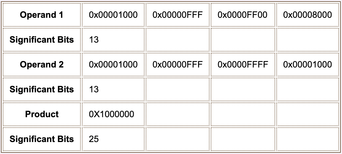
Write a program that multiplies the contents of two registers which you have initialized using an immediate operand with the ori instruction. Determine (by inspection) the number of significant bits in each of the following numbers, represented in two's complement. Use the program to form their product and then determine the number of significant bits in it.
Exercise 4 (*)
Write a program that determines the value of the following expression:
(x*y)/z
Use x = 1600000 (=0x186A00), y = 80000 (=0x13880), and z = 400000 (=61A80). Initialize three registers to these values. Since the immediate operand of the ori instruction is only 16 bits wide, use shift instructions to move bits into the correct locations of the registers.
Choose wisely the order of multiply and divide operations so that the significant bits always remain in the lo result register.
Memory Access: Loading and Storing Registers
This chapter discusses how to copy data from memory into registers, and how to copy data to memory from registers.
Chapter Topics:
- Load and store
- Data alignment
- Byte order (little endian and big endian)
- The
lwandswinstructions - The load delay slot
- Base registers and address calculation
- The
luiinstruction - Symbolic addresses
Question 1
(Review:) What is the name of the operation that copies data from main memory into a register?
Answer
A register is loaded from memory.
Load and store
The operands for all arithmetic and logic operations are contained in registers. To operate on data in main memory, the data is first copied into registers. A load operation copies data from main memory into a register. A store operation copies data from a register into main memory .
When a word (4 bytes) is loaded or stored the memory address must be a multiple of four. This is called an alignment restriction. Addresses that are a multiple of four are called word aligned. This restriction makes the hardware simpler and faster.
The lw instruction loads a word into a register from memory.
The sw instruction stores a word from a register into memory.
Each instruction specifies a register and a memory address (details in a few pages).
Question 2
Which of the following addresses are word aligned?
0x000AE4300x000144320x000B07370x0E0D8844
Hint: how can you multiply by four in binary?
Answer
Any integer that is a multiple of 4 looks like 4*N for some N.
How can you multiply by four in binary? By shifting left 2 positions. So a multiple of 4 looks like some N shifted left two positions. So the low order two bits of a multiple of 4 are both 0.
0x000AE430Yes0x00014432No0x000B0737No0x0E0D8844Yes
Big endian and little endian
A load word or store word instruction uses only one memory address. The lowest address of the four bytes is the address of a block of four contiguous bytes.
How is a 32-bit pattern held in the four bytes of memory? There are 32 bits in the four bytes and 32 bits in the pattern, but a choice has to be made about which byte of memory gets what part of the pattern. There are two ways that computers commonly do this:
- Big Endian Byte Order: The most significant byte (the "big end") of the data is placed at the byte with the lowest address. The rest of the data is placed in order in the next three bytes in memory.
- Little Endian Byte Order: The least significant byte (the "little end") of the data is placed at the byte with the lowest address. The rest of the data is placed in order in the next three bytes in memory.
In these definitions, the data, a 32-bit pattern, is regarded as a 32-bit unsigned integer. The "most significant" byte is the one for the largest powers of two: . The "least significant" byte is the one for the smallest powers of two: .
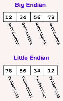
For example, say that the 32-bit pattern 0x12345678 is stored at address 0x00400000. The most significant byte is 0x12; the least significant is 0x78.
Within a byte the order of the bits is the same for all computers (no matter how the bytes themselves are arranged).
Question 3
What bit pattern that is contained in the byte at the big end of this 32-bit word:
0x001122AA
Answer
The big end is the byte that contains 0x00.
Notice that "big end" refers to position within the word, not the value of the byte.
Byte order of MIPS and SPIM
Within a byte, for all processors, bit 7 is the most significant bit. So the big end byte looks the same for both byte orderings. Usually in printed material this bit is shown at the left, as in 00010010.
Except when discussing byte ordering, the "big end" byte is called the "high-order byte" or the "most significant byte".
The MIPS processor chip can be set up in hardware to use either byte ordering. A computer system designer makes whatever choice best fits the rest of the components in the computer system.
The SPIM simulator uses the byte ordering of the computer it is running on.
- Intel 80x86: little-endian.
- recent Macintosh: little-endian.
- older Macintosh: big-endian.
The examples in these notes were done on a Windows/Intel computer. If you are using a older Macintosh there will be occasional differences.
Question 4
Here is a bit pattern, with the most significant bits written on the left (as is usual in print): 0xFF00AA11. Copy the bytes to memory using big endian and little endian orders:
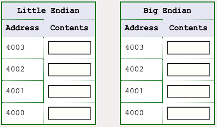
Answer
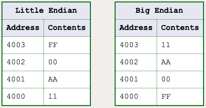
0xFF00AA11
To answer the question, remember:
- The address used for a group of bytes is the smallest address of the four.
- What goes in that byte is:
- Big Endian: the big end
- Little Endian: the little end
- The remaining three bytes are filled in sequence.
Probability problems
When a word is loaded from memory, the electronics puts the bytes into the register in the correct order. Operations (such as addition) inside the processor use the same order. When the register is stored to memory the bytes are written in the same order.
As long as the electronics is consistent, either byte order works. Usually you don't need to think about which order is used.
However, when data from one computer is used on another you do need to be concerned. Say that you have a file of integer data that was written by an old mainframe computer. To read it correctly, you need to know (among other things):
- The number of bits used to represent each integer.
- The representational scheme used to represent integers (two's complement or other).
- Which byte ordering (little or big endian) was used.
Question 5
Data is sent across the Internet as groups of bit patterns (of course!) Does the byte ordering matter with Internet data?
Answer
Yes.
The details are slightly complicated. But rest assured that there are international standards for this.
MIPS addresses
The MIPS instruction that loads a word into a register is the lw instruction. The store word instruction is sw. Each must specify a register and a memory address. A MIPS instruction is 32 bits (always). A MIPS memory address is 32 bits (always). How can a load or store instruction specify an address that is the same size as itself?
An instruction that refers to memory uses a base register and an offset.
- The base register is a general purpose register that contains a 32-bit address.
- The offset is a 16-bit signed integer contained in the instruction.
- The sum of the address in the base register with the (sign-extended) offset forms the memory address.
Here is the load word instruction in assembly language:
lw   d,off(b)       # $d <-- Word from memory address b+off
                    # b is a register. off is 16-bit two's complement.
                    # (The data from memory is available in $d after
                    #  a one machine cycle delay.)
At execution time two things happen:
- An address is calculated by adding the base register b with the offset
off - Data is fetched from memory at that address
Because it takes time to copy data from memory, it takes two machine cycles before the data is available in register $d. In terms of assembly language this means the instruction immediately after lw should not use $d.
Question 6
Write the instruction that loads the word at address 0x00400060 into register $8. Assume that register $10 contains 0x00400000.
lw $8, ______ ( ______ )
Answer
0x00400060 --- address of data
0x00400000 --- address in $10
$8         --- destination register
The instruction is:
lw $8,0x60($10)
Machine instruction for load word
Here is the machine code version of the instruction. It specifies the base register, the destination register, and the offset. It does not directly contain the memory address.
100011  01010 01000 0000 0000 0110 0000 -- fields of the instruction

lw      $10   $8     0    0    6    0
opcode  base  dest        offset        -- meaning of the fields

lw      $8, 0x60($10)                   -- assembly language
Here is how this instruction is executed:
The 32-bit address in $10 is:
0x00400000The offset is sign-extended to 32 bits:
0x00000060The memory address is the 32-bit sum of the above:
0x00400060Main memory is asked for data from that address.
After a one machine cycle delay the data reaches
$8.$8 = The 4 bytes
There is a one machine cycle delay before the data from memory is available. Reaching outside of the processor chip into main memory takes time. But the processor does not wait and executes one more instruction while the load is going on.
This is the load delay slot. The instruction immediately after a lw instruction should not use the register that is being loaded. Sometimes the instruction after the lw is a no-operation instruction.
Question 7

Look at registers $12 and $13 and memory (above). Write the instruction that puts the value 0x00000004 into register $12.
- Register
$12contains0xFFFFFFFF - Register
$13contains0x00040000
lw $ ______, ______ ($ ______ )
Answer
lw $12, 0x10($13)
The original value in $12 is irrelevant; it is replaced with a value from memory (memory remains unchanged).
Store word instruction
The store word instruction, sw, copies data from a register to memory. The register is not changed. The memory address is specified using a base/register pair.
sw   t,off(b)       # Word at memory address (b+off) <— $t
                    # b is a register. off is 16-bit two's complement.
As with the lw instruction, the memory address must be word aligned (a multiple of four).
Question 8

Look at registers $12 and $13 and memory (above). Write the instruction that puts the word 0xFFFFFFFF into memory location 0x0004000C.
- Register
$12contains0xFFFFFFFF - Register
$13contains0x00040014
sw $ ______, ______ ($ ______ )
Hint: it is OK to specify the 16-bit offset as a signed decimal integer.
Answer
sw $12 , 0xFFF8($13) or sw $12 , -8($13)
The second answer is the preferred version in assembly language source. It assemble into the same machine instruction as the first version.
Setting up the base register

The first instruction of the answer expresses minus eight using 16-bit two's complement. This is the bit pattern that is actually contained in the machine instruction. This is awkward to read and to calculate. The second instruction uses signed decimal notation to specify minus eight. The assembler translates this assembler instruction into exactly the same machine instruction as the first assembler instruction.
By using a 32-bit base register and an offset a 32-bit lw or sw instruction can reference all of memory.
But how does the base address get into the base register? This is where the lui (load upper immediate) instruction is useful. lui copies its 16-bit immediate operand to the upper two bytes (16 bits) of the designated register.
lui  d,const  # upper two bytes of $d <— two byte const
              # lower two bytes of $d <— 0x0000
Sometimes this is all that you need. For example, say that memory is as in the picture, and that you want to load the word at 0x00040010 into $12. The lui instruction can set up the base register.
Question 9
lui $13, 0x____

lw  $12, 0x10($13)
Complete the lui instruction so that the base register contains the address 0x00040000.
Answer
lui $13, 0x0004
lw  $12, 0x10($13)
After the lui instruction $13 contains 0x00040000. To get to the address we need, use an offset of 0x10.
Filling in the bottom half

By using the lui instruction, the base register can be loaded with multiples of 0x00010000. But often you want a more specific address in the base register. Use the ori instruction to fill the bottom 16 bits.
ori d,s,imm
Recall that ori zero-extends imm to 32 bits then does a bitwise OR of that with the contents of register $s. The result goes into register $d.
Question 10
Say that memory is as above. The lw instruction (below) loads the word at 0x0060500C into $12.
lui $13, 0x____

ori $13, $13, 0x____

lw  $12, 0xC($13)
Complete the instruction sequence so that the base register contains the address 0x00605000, which will be used with a displacement of 0x0C.
Answer
lui $13, 0x0060
ori $13, $13, 0x5000
lw  $12, 0xC($13)
Alternate sequence
The above ori instruction "fills in" the lower 16 bits of register $13 by doing the following:
$13 after lui           :  0000 0000 0110 0000 0000 0000 0000 0000
zero-extended imm. op.  :  0000 0000 0000 0000 0101 0000 0000 0000
result of bitwise OR    :  0000 0000 0110 0000 0101 0000 0000 0000
Other sequences of instructions also will work. Choose whichever method works best in the context of the rest of the program.
Because the "upper half" of an address is 16 bits and the offset of the lw can hold the 16 bit "lower half," the two in combination can address any byte of memory.
The problem was to load $12 with the word at address 0x0060500C. Here is another way to do it: Split the address into halves: 0x0060 and 0x500C. Load the top half into $13 and use the bottom half as the offset.
lui $13, 0x0060
lw  $12, 0x500C($13)
Since the ori instruction is used often with the destination register as one of the operands, there is a shorthand instruction in assembly language.
ori  $d,const  # assembles to the same machine
               # instruction as ori $d,$d,const
Question 11
Do the following two assembly instructions assemble to the same machine instruction?
ori  $10,$10,0x00C4

ori  $10,$0, 0x00C4
Answer
NO. The first instruction keeps the upper half of $10 the same and ORs in some bits in the lower half.
The second instruction replaces all 32 bits of $10 with the zero-extended immediate operand.
ori  $10,$10,0x00C4

ori  $10,$0, 0x00C4
Assembly arrays

An array of int is implemented as a sequence of words in successive word-aligned memory locations. For example, the diagram shows a possible implementation of:
int data[] = {0, 1, 2, 3, 4, 5};
The above is expressed using the language C, but you don't have to know any C to understand this page. The declaration creates an array of six elements and initializes them to the integers zero through five.
In C, you don't don't usually know what addresses are used for an array. In assembly language you do. Details in a few pages.
Question 12
Assume that you have an array that starts at address 0x00605000 as in the picture.
What is the most sensible address to have in the base register for processing this array?
Answer
The address of data[0]: 0x00605000. In fact, in ANSI C, the identifier for an array (in this case data) stands for the address of its first element. At run time this address will likely be in a base register.
Example program
You may be thinking that there has got to be an easier way to load a register from memory. At the machine language level there is not. However, the assembler has features that make it much easier to write lw and sw instructions. These are discussed in a later chapter.
Let us start on an example program. The program is to evaluate the polynomial 5x^2 -12x + 97. The value x is located in memory. Store the result at location poly in memory.
Question 13
How many lw instructions will be needed?
How many sw instructions will be needed?
Answer
- How many
lwinstructions will be needed?- One, near the start of the program to load
xinto a register.
- One, near the start of the program to load
- How many
swinstructions will be needed?- One, near the end of the program to save the result in
poly.
- One, near the end of the program to save the result in
Symbolic address
## poly.asm
##
## evaluate  5x^2 -12x + 97
##

        .text
        .globl  main

main:

        . . . . many instructions

        .data
                             # In SPIM, the data section
                             # starts at address 0x10000000
x:      .word   17           # The base register points here.
poly:   .word   0

## End of file
In the description of this problem, memory locations are called x and poly. Of course, at run time, addresses are 32-bit patterns.
In assembly language source code, it is convenient to use names for memory locations. These names are called symbolic addresses.
One of the most important features of an assembler is support for symbolic addresses. In the following example we will ignore some of this support in favor of explaining how the hardware instructions work.
In the above (incomplete) sample program, x is a symbolic address. It corresponds to the address where, at run-time, four bytes hold a two's complement 17.
The assembler directive .data means: here is the start of the data section of memory.
The assembler directive .word means: put a 32-bit two's complement integer here. The integer is specified using base 10 (by default).
In the above, the .word 17 calls for a 32-bit two's complement representation of an integer that in base 10 is "17". The assembler converts the representation into the appropriate bit pattern.
You can also specify the bit pattern using the hexadecimal name for the pattern. .word 0x11 does exactly the same thing as .word 17.
Question 14
The assembler in SPIM automatically assembles the .data section starting at address 0x10000000.
- What address corresponds to the symbolic address
x? - What address corresponds to the symbolic address
poly?
Answer
The assembler in SPIM automatically assembles code starting at address 0x10000000.
- What address corresponds to the symbolic address
x?0x10000000 - What address corresponds to the symbolic address
poly?0x10000004
Here is what this part of the SPIM simulation looks like:
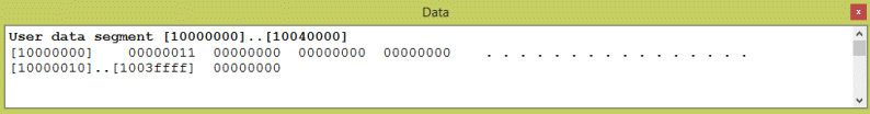
More code
The program must load a register with data from memory, and, at the end, store a result back to memory. The above program fragment does this, when you complete it.
The register use table in the documentation summarizes how registers are used in this program. When you program, decide on the registers you need and what they are used for. Then write down your decisions! This is crucial for getting things correct.
A register where a value is built up after several calculations is called an accumulator. (Some old processors have a single, special register that is used for this purpose. But MIPS has many general purpose registers for this).
Remember that data loaded from memory is not available to the instruction following the load. The instruction after a lw, in the "load delay slot", should not try to use the loaded data.
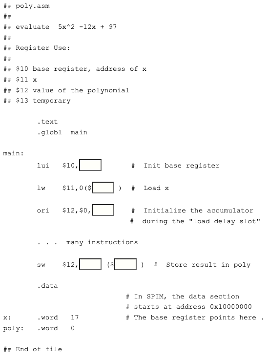
Question 15
Fill in the blanks. Look at the previous answer to help with the lui instruction. Use it to load the upper half of the base register with the upper half of the first data address.
Answer
See below.
Second term
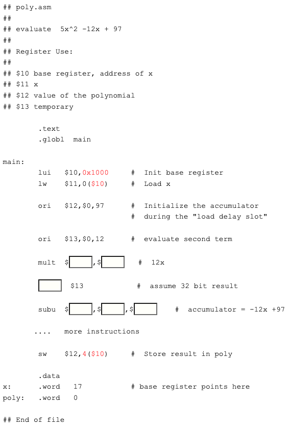
Since SPIM starts the data section at 0x10000000, register $10 can be loaded with the first address of the data section using the lui instruction. The low order sixteen bits of the address are all zero. The address of x is an offset of zero from that base address.
The location for the result is at an offset of four from the base address.
Now fill in the blanks so that the second term is evaluated and added to the accumulator.
Question 16
Fill in the blanks.
Answer
All blanks filled, as below.
Third term
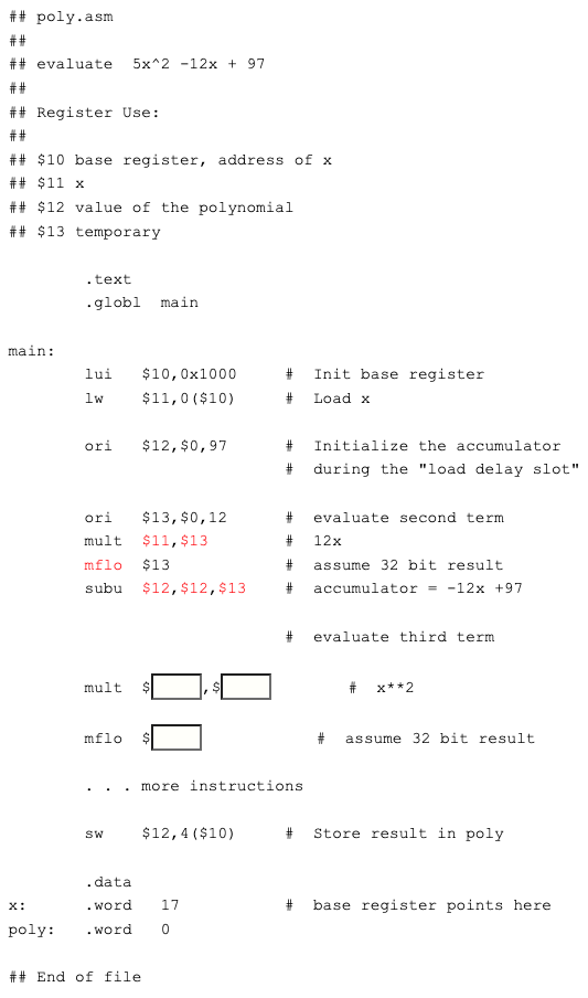
At this point all we need to do is square x, multiply by five, and add the result to the accumulator.
After squaring x you don't need its value anymore, so x**2 can be put back into register $11.
Question 17
Fill in the blanks.
Answer
See below.
More of the third term
Here is the rest of the program:
Happily, after filling in the blanks, the program is finished.
Question 18
Fill in the blanks.
Answer
See below.
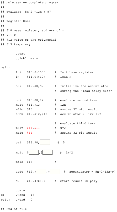
Complete program
## poly.asm -- complete program
##
## evaluate  5x^2 -12x + 97
##
## Register Use:
##
## $10 base register, address of x
## $11 x
## $12 value of the polynomial
## $13 temporary

        .text
        .globl  main

main:
        lui   $10,0x1000     #  Init base register
        lw    $11,0($10)     #  Load x

        ori   $12,$0,97      #  Initialize the accumulator
                             #  during the "load delay slot"

        ori   $13,$0,12      #  evaluate second term
        mult  $11,$13        #  12x
        mflo  $13            #  assume 32 bit result
        subu  $12,$12,$13    #  accumulator = -12x +97

                             #  evaluate third term
        mult  $11,$11        #  x^2
        mflo  $11            #  assume 32 bit result
        ori   $13,$0,5       #  5
        mult  $11,$13        #  5x^2
        mflo  $13            #
        addu  $12,$12,$13    #  accumulator = 5x^2-12x+97

        sw    $12,4($10)     #  Store result in poly

        .data
x:      .word   17           #  Edit this line to change the value of x
poly:   .word   0            #  Result is placed here.

## End of file
Here is the complete program. You may wish to copy it to the clipboard and paste it into your text editor. Now you can save it to a file and run it with SPIM.
Of course, the program should be tested with a careful selection of values for x. A production quality program would document the upper and lower bounds for x.
Question 19
Suggest three values for x for use in testing.
Answer
0, 1, -1. Of course you don't stop there, but running with these three values often reveals problems.
A run of the program
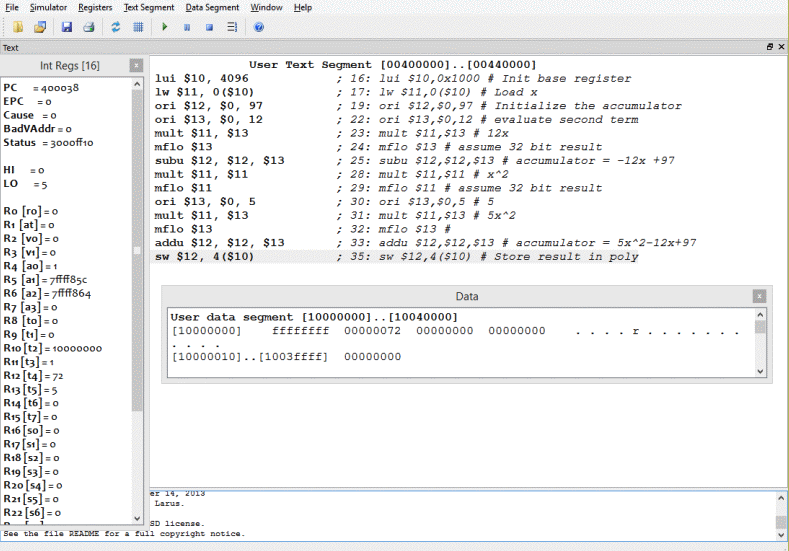
Here is a run of the program after x was changed to -1. The result, 0x72 = 114_10 is correct. As always, running is done by single-stepping (pushing F10). The PC is initialized to 0x00400000.
Create a source file and play around with the program. Put some bugs into the program and see what they do. Experimentally determine the range allowed for x.
Question 20
How can you solve for the allowed range of x?
Answer
The result, poly must fit into 32 bits, two's complement. So -2^31 ≤ 5x^2 -12x + 97 ≤ 2^31 - 1. Further algebraic fussing gives the range of x.
Chapter quiz
Instructions: For each question, choose the single best answer. Make your choice by clicking on its button. You can change your answers at any time. When the quiz is graded, the correct answers will appear in the box after each question.
Question 1
What operation copies data from main memory into a general purpose register?
- (A) load
- (B) store
- (C) move
- (D) add
Answer
A
Question 2
Which one of the following addresses is word aligned?
- (A)
0x01234567 - (B)
0x00FA0700 - (C)
0x77000003 - (D)
0x00000042
Answer
B
Question 3
Say that four bytes in main storage contain bits that represent a 32-bit integer. What is the address is used for this integer?
- (A) The address of the byte with the highest address of the four.
- (B) The address of each byte is used.
- (C) Only one byte at a time can be addressed.
- (D) The address of the byte with the lowest address of the four.
Answer
D
Question 4
Here is a 32-bit pattern: 0x00224477. This pattern is to be stored in main memory using bytes at addresses 0x10000000, 0x10000001, 0x10000002, and 0x10000003. On a big endian processor, what bit pattern is contained in address 0x10000000?
- (A)
0x00 - (B)
0x22 - (C)
0x44 - (D)
0x77
Answer
A
Question 5
A lw is to load register $5 from location 0x0040000C in memory. Register $10 contains 0x00400000. Write the assembly language instruction:
- (A)
lw $10,0x0C($10) - (B)
lw $10,0x0C($5) - (C)
lw $5,0x0C($10) - (D)
lw $5,0x0C(400000)
Answer
C
Question 6
Register $10 contains 0x10000000. Beginning at that address there are five integers in a row. Write the instruction that loads the last integer into register $7.
- (A)
lw $7, 50($10) - (B)
lw $7, 20($10) - (C)
lw $7, 16($10) - (D)
lw $7, 40($10)
Answer
C
Question 7
Register $5 contains the address 0x10000100. Write the instruction that loads the four bytes that precede this address into register $7.
- (A)
lw $7, 4($5) - (B)
lw $7, -4($5) - (C)
lw $5, 4(-$5) - (D)
lw $7, 0($5-4)
Answer
B
Question 8
Write the assembly instruction that fills register $10 with 0x10000000
- (A)
lui $10, 0x1000 - (B)
lui $10, 0x10000000 - (C)
ori $10, $0, 0x10000000 - (D)
ori $10, $10, 0x1000
Answer
A
Question 9
Say that somehow register $10 has been loaded with the address 0x10000000. Write the instruction that alters $10 so that it contains 0x100000F0.
- (A)
ori $10, $0, 0x00F0 - (B)
or $10, $10, 0x00F0 - (C)
ori $10, $10, 0x00F0 - (D)
andi $10, $10, 0x00F0
Answer
C
Question 10
Examine the following program fragment.
## fragment.asm

        .text
        .... program statements ...

        .data

value:  .word 23
result: .word 97
Assuming that SPIM starts the data section at address 0x10000000, what address does symbolic address result represent?
- (A)
0x10000004 - (B)
0x10000000 - (C)
0x10000003 - (D)
0x00000097
Answer
A
Question 11
Refer back to the previous fragment. We want register $8 to contain the address of the first byte in the data section. What instruction does this?
- (A)
lui $8,1000 - (B)
lui $8,$8,0x1000 - (C)
lui $8,0x10000000 - (D)
lui $8,0x1000
Answer
D
Question 12
Refer back to the previous fragment. Assume that register $8 contains the address 0x10000000. What instruction stores the contents of register $4 into location result?
- (A)
sw $4,4($8) - (B)
sw $4,0($8) - (C)
sw $4,0x0($8) - (D)
sw $4,$0x05($8)
Answer
A
Programming exercises
For these programming exercises, use only those instructions that have been discussed so far in these notes:
add | lw | sll |
addi | mfhi | sra |
addiu | mflo | srl |
addu | mult | sub |
and | multu | subu |
andi | nor | sw |
div | or | xor |
divu | ori | xori |
lui |
In the Settings menu of SPIM set Bare Machine ON, Allow Pseudo Instructions OFF, Load Trap File OFF, Delayed Branches ON, Delayed Loads ON, Mapped IO OFF, Quiet OFF.
Run the programs by setting the value of the PC to 0x400000 and then single stepping (pushing F10) or by multiple stepping (push F11 and enter a number of steps). Observing the results in the SPIM window.
Exercise 1
Modify exercise 1 of the previous chapter so that the value x is in memory. Store the value of the polynomial back to memory. The program will be similar to poly.asm from this chapter. Evaluate the polynomial:
3x2 + 5x - 12Use symbolic addresses x and poly. Assume that the value in x is small enough so that all results fit into 32 bits. Since load delays are turned on in SPIM be careful what instructions are placed in the load delay slot.
Verify that the program works by using several initial values for x. Use x = 0 and x = 1 to start since this will make debugging easy. Then try some other values, such as x = 10 and x = -1.
Optional: write the program following the hardware rule that two or more instructions must follow a mflo instruction before another mult instruction. Try to put useful instructions in the two slots that follow the mflo.
Exercise 2
Evaluate the expression:
17xy - 12x - 6y + 12
Use symbolic addresses x, y, and answer. Assume that the values are small enough so that all results fit into 32 bits. Since load delays are turned on in SPIM be careful what instructions are placed in the load delay slot.
Verify that the program works by using several initial values for x and y. Use x=0, y=1 and x=1, y=0 to start since this will make debugging easy. Then try some other values. As an option, follow the precaution for multiplication, as above.
Exercise 3 (*) - Horner's Method
Evaluate the polynomial:
6x3 - 3x2 + 7x + 2Get the value for x from symbolic addresses x. Store the result at symbolic address poly. Assume that the values are small enough so that all results fit into 32 bits. Since load delays are turned on in SPIM be careful what instructions are placed in the load delay slot.
Evaluate the polynomial by using Horner's Method. This is a way of building up values until the final value is reached. First, pick a register, say $7, to act as an accumulator. The accumulator will hold the value at each step. Use other registers to help build up the value at each step.
First, put the coefficient of the first term into the accumulator:
6
Next, multiply that value by x:
6x
Add the coefficient of the next term:
6x - 3
Next, multiply that sum by x:
6x2 - 3xAdd the coefficient of the next term:
6x2 - 3x + 7Next, multiply that sum by x:
6x3 - 3x2 + 7x Finally, add the coefficient of the last term:
6x3 - 3x2 + 7x + 2Evaluating the polynomial in this way reduces the number of steps (and the amount of code). If you want to save time, write and debug each step before moving on to the next. When you reach the final step you should have a working, debugged program.
Verify that the program works by using several initial values for x. Use x=1 and x=-1 to start since this will make debugging easy. Then try some other values. As an option, follow the precaution for multiplication.
Exercise 4 (**) - more Horner's Method
Evaluate the following polynomial using Horner's method: ax3 + bx2 + cx + d
Now the values for the coefficients a, b, c, d as well as for x come from the .data section of memory:
       .data
x:     .word    1
a:     .word   -3
b:     .word    3
c:     .word    9
d:     .word  -24
Load a base register with the address of the first byte of the .data section. Calculate (by hand) the displacement needed for each of the values in memory and use it with a lw instruction to get values from memory. In a later chapter you will find a much more convenient way to load and store values using symbolic addresses. But don't do this now.
More Memory Access: Bytes and Halfwords
This chapter discusses some more instructions that load registers (from memory) and that store registers (to memory). These instructions are used less frequently than lw and sw.
Chapter Topics:
- Load byte and store byte:
lb,lbu, andsb - Load halfword and store halfword:
lh,lhu, andsh - Arithmetic with less than 32 bits.
Question 1
(Review:) What is the smallest addressable unit of main memory?
Answer
A byte
Loading a single byte
There are two instructions that load a byte from a memory address. The address of the byte is calculated at run time by adding an offset to a base register (just as with the load word and store word instructions). The instructions differ in how the 8-bit byte is put into the 32-bit register.
lb   t,off(b)  # $t <— Sign-extended byte
               # from memory address b+off
               # b is a base register.
               # off is 16-bit two's complement.
The lb instruction loads the byte from memory into the low order eight bits of the register. These are bits 0-7 of the register. Then it copies bit 7 to bits 8-31 of the register (all bits to the left of bit 7).
Another way to say this is that the lb instruction loads the register with a 32-bit sign extended version of the byte at the designated address. Use the lb instruction when the byte is regarded as an 8-bit signed integer in the range -128...+127 and you want a 32-bit version of the same integer.
lbu   t,off(b) # $t <— Zero-extended byte
               # from memory address b+off
               # b is a base register.
               # off is 16-bit two's complement.
The lbu instruction fills bits 8-31 of the register with zeros. Use this instruction when the byte is regarded as a ascii character or 8-bit unsigned integer.
Question 2
- Memory at
0x10000007contains the byte0xA4 - Register
$8contains0x10000000
What is put in register $10 when the following instruction is executed:
lb    $10,7($8)

_______________
What is put in register $12 when the following instruction is executed:
lbu    $12,7($8)

_______________
Answer
$10 = 0xFFFFFFA4
Bit 7 of 0xA4 is 1, so lb extends that bit to all high order three bytes of $10.
$12 = 0x000000A4
lbu zero-extends the byte from memory.
Storing a single byte
Loading and storing bytes is used for processing text and for low-level systems programs (such as assemblers and operating systems). Graphics programs, also, make frequent use of these operations. Both operations could be done using lw and sw along with bit manipulation instructions, but it is convenient to have byte-length load and store.
There is an instruction for storing a byte:
sb    t,off(b)   # The byte at off+b <— low-order
                 # byte from register $t.
                 # b is a base register.
                 # off is 16-bit two's complement.
There is no need for two "store byte" instructions. Whatever is in the low-order byte of the register is copied to memory. The rest of the register is ignored. Of course, the register does not change.
Question 3
- Memory at
0x10000519contains the byte 0x44 - Register
$8contains0x10000400 - Register
$10contains0xFA034183
Write the instruction that replaces the "0x44" in memory with "0x83".
sb _____, _____ ( _____ )
Answer
sb $10,0x119($8)
All addresses great and small
There are no alignment requirements for the three instructions: lb, lbu, and sb. Any byte in memory that is acceptable for program data can be used. This is fortunate since character strings are usually stored in successive bytes.
Byte load and store instructions are often used for input and output with media that must be used on many types of systems. Often the data written to magnetic tape by one government agency is used by other agencies using different computers. To make the data transportable, the format of the data is described byte by byte. The format must be followed, regardless of the inherent byte order of the computers writing or reading the data.
Question 4
A particular data tape requires big-endian integers. Data is assembled in memory in a buffer before it is written out to the tape. The I/O buffer for the tape starts at address 0x10000000. Complete the following instructions so that the integer in register $9 is stored in the four bytes starting at address 0x10000000. Put the most significant byte (the "big end") at the starting address.
lui  $8,0x1000          # $8 is base register

sb   $9, ____ ($8)      # least significant byte

srl  $9,$9, ____        # move next byte to low order

sb   $9, ____ ($8)      # bits 8-15

srl  $9,$9, ____        # move next byte to low order

sb   $9, ____ ($8)      # bits 16-23

srl  $9,$9, ____        # move next byte to low order

sb   $9, ____ ($8)      # most significant byte
Answer
lui  $8,0x1000      # $8 is base register
sb   $9,3($8)       # least significant byte
srl  $9,$9,8        # move next byte to low order
sb   $9,2($8)       # bits 8-15
srl  $9,$9,8        # move next byte to low order
sb   $9,1($8)       # bits 16-23
srl  $9,$9,8        # move next byte to low order
sb   $9,0($8)       # most significant byte
Tape writer
The least significant byte of the register is written to memory first because its location in the register is where sb instruction needs it. The data in the buffer should be in big-endian order, so this (little end) goes into offset 3 from the base address.
Now the remaining bytes of $9 are shifted into the right-most byte one by one and written to memory. Here is a complete version of the program:
## endian.asm
##
## copy $9 to memory in big-endian order
##
## Register Use:
## $8  --- first byte of the tape buffer
## $9  --- 4-byte integer

      .text
      .globl  main

main:
      lui  $9,0x1234      # put data in $9
      ori  $9,0x5678      #
      lui  $8,0x1000      # $8 is base register
      sb   $9,3($8)       # least significant byte
      srl  $9,$9,8        # move next byte to low order
      sb   $9,2($8)       # bits 8-15
      srl  $9,$9,8        # move next byte to low order
      sb   $9,1($8)       # bits 16-23
      srl  $9,$9,8        # move next byte to low order
      sb   $9,0($8)       # most significant byte

      .data
tape:                     # base register points here
      .space 1024         # tape buffer (1K bytes)
The .space directive reserves bytes in memory, in this case 1024_10 bytes. Pretend this is the buffer from which a tape record will be written. The example program deals with just the first four bytes, but in a real program all 1K bytes of the buffer would be collected before the buffer was written to tape.
Question 5
What is the symbolic address of the first byte of the .data section? What main storage address will it have at run time?
Answer
- What is the symbolic address of the first byte of the
.datasection?tape - What main storage address will it have at run time?
0x10000000
The main storage address for the first byte of the data section is 0x10000000 by default (of the SPIM assembler). There is nothing in the program that says this.
A run of the program
The SPIM display shows data in groups of 4-byte words with the most significant byte on the left. This makes the data readable by humans. Within each group of four, the byte with the lowest address is on the right. Here is how SPIM looks after the low-order byte of the register has been stored to the buffer:
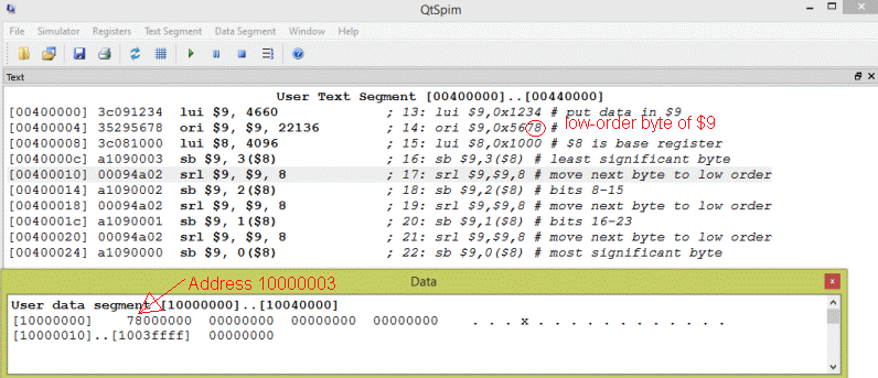
Register $9 has been loaded with the bit pattern 0x12345678.
The low-order byte has been stored where it should be in memory, although you have to look at the display carefully to see this. (Recall that SPIM displays each group of four bytes in backwards order to make reading little-endian integers easier.)
Question 6
Which byte of $9 should go into address $0x10000000?
Answer
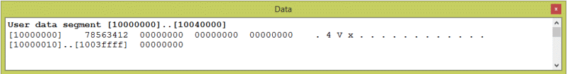
0x12 — the "big end" of an integer goes into the first address of a group of bytes with big-endian byte order.
Eventually, after a few more right shifts, it gets there.
Loading halfwords
A MIPS halfword is two bytes. This, also, is a frequently used length of data. In ANSI C, a short integer is usually two bytes. So, MIPS has instructions to load halfword and store halfwords.
There are two load halfword instructions. One extends the sign bit of the halfword in memory into the upper two bytes of the register. The other extends with zeros.
lh   t,off(b)   # $t <— Sign-extended halfword
                # starting at memory address b+off.
                # b is a base register.
                # off is 16-bit two's complement.

lhu  t,off(b)   # $t <— zero-extended halfword
                # starting at memory address b+off.
                # b is a base register.
                # off is 16-bit two's complement.
Halfword addresses must be halfword aligned. Attempting to load a halfword from an unaligned address will cause a trap.
Question 7
How can you tell if an address is halfword aligned?
Answer
It is a multiple of two. Such addresses have a zero in the low-order bit.
Storing halfwords
Only one store halfword instruction is needed. The low-order two bytes of the designated register are copied to memory, no matter what the upper two bytes are. Of course, the register is not changed when its data is copied to memory.
sh    t,off(b)    # Halfword at off+b <— low-order
                  # two bytes from $t.
                  # b is a base register.
                  # off is 16-bit two's complement.
MIPS arithmetic instructions that use registers always use full registers, regardless of how data was loaded into the register. For example, an addu instruction does a full 32-bit addition even if one of the operand registers was loaded with lh (or lb).
Question 8
Perform these two addition problems:
0110 1110         0000 0000 0000 0000 0000 0000 0110 1110
1100 0110         0000 0000 0000 0000 0000 0000 1100 0110
---------         ---------------------------------------
Answer
11  1 11                                       1 1  1 11
 0110 1110         0000 0000 0000 0000 0000 0000 0110 1110
 1100 0110         0000 0000 0000 0000 0000 0000 1100 0110
 —————————         ———————————————————————————————————————
 0011 0100         0000 0000 0000 0000 0000 0001 0011 0100
All arithmetic is 32-bits
MIPS has no instructions for eight-bit arithmetic. Say that there were two operands in the low order bytes of two registers (as above). A fullword addition of these registers puts the same results in the low-order byte that an 8-bit addition would. However, the carry out of the high-order bit of the eight bits becomes bit 8 of the 32-bit result. Further bit manipulation instructions can be used to deal with it.
So there is no need for eight-bit arithmetic instructions, nor for halfword arithmetic instructions.
Question 9
Now divide the sum we just calculated by two. Do this by shifting right one place:
0011 0100 0000 0000 0000 0000 0000 0001 0011 0100
Answer
0011 0100         0000 0000 0000 0000 0000 0001 0011 0100


0001 1010         0000 0000 0000 0000 0000 0000 1001 1010
The 8-bit result is different from the low order byte in the 32-bit result. Of course, if we had cleared the carry bit in bit 8 of the 32-bit sum before the shift the two bytes would be identical.
Low-order result not always correct
In general the low order byte after several 32-bit operations is not the same as would result from several true 8-bit arithmetic operations.
These are problems that compilers face. For example, ANSI C short int variables should behave the same way on all computers. But 16-bit math does not behave the same way on all computer architectures! When C is compiled for MIPS, several extra machine operations must be inserted between each arithmetic operation when the operands are short ints. On MIPS (and some other computers) 16-bit arithmetic is much slower than 32-bit arithmetic.
Naive programmers sometimes use short ints with the expectation that their program will run faster. Depending on the hardware and the compiler, the opposite might be true!
Question 10
Cryptography programs often treat characters as 8-bit integers and transform them with arithmetic operations. Suppose a cryptography program is written in C for a Windows system. When compiled on a Macintosh system it runs, but produces different results! You have been given the job of making the Mac version work identically to the Windows version. What must you do?
Answer
Probably the problem is with differences in small integer arithmetic between the two systems. You will have to carefully look at variable declarations in the program and will have to study the arithmetic. To make the Mac version identical to the Windows version, you may have to write parts of it in assembly.
Chapter quiz
Instructions: For each question, choose the single best answer. Make your choice by clicking on its button. You can change your answers at any time. When the quiz is graded, the correct answers will appear in the box after each question.
Question 1
What is the smallest addressable unit of main memory?
- (A) byte
- (B) bit
- (C) nibble
- (D) halfword
Answer
A
Question 2
Which of the following instructions does sign extension?
- (A)
lbu - (B)
lb - (C)
add - (D)
lhu
Answer
B
Question 3
Say that:
- Memory at
0x10000000contains 0x80 - Register
$5contains0x10000000
What is put in register $8 after lb $8,0($5) is executed?
- (A)
0x88888880 - (B)
0x00000080 - (C)
0x80000000 - (D)
0xFFFFFF80
Answer
D
Question 4
What instruction is used to store a byte to memory?
- (A)
sb - (B)
sbu - (C)
lb - (D)
sw
Answer
A
Question 5
Say that:
- Memory at
0x10000000contains0x80 - Memory at
0x10000001contains0x00 - Register
$5contains0x10000000
Say that the MIPS chip is running in little-endian mode (as does SPIM on an Intel computer). What is put in register $8 after lh $8,0($5) is executed?
- (A)
0xFFFFFF80 - (B)
0x88888880 - (C)
0x00000080 - (D)
0x80000000
Answer
C
Question 6
Say that:
- Memory at
0x10000000contains0x80 - Memory at
0x10000001contains0x00 - Register
$5contains0x10000000
Say that the MIPS chip is running in big-endian mode (as does SPIM on an Apple computer). What is put in register $8 after lh $8,0($5) is executed?
- (A)
0xFFFF8000 - (B)
0xFFFFFF80 - (C)
0x00000080 - (D)
0x80000000
Answer
A
Question 7
Which one of the following address are half-word aligned?
- (A)
0x01004F35 - (B)
0x01004F37 - (C)
0x01004F3A - (D)
0x01004F3F
Answer
C
Question 8
Say that data is in memory and the base register has been initialized correctly. You have the following program:
lh     $5,0($10)
lb     $6,4($10)
addu   $7,$5,$4
What does the addu instruction do?
- (A) It performs the binary addition algorithm on whatever 32-bit patterns are in registers
$4and$5. - (B) It performs a 16-bit addition because that is the size of the largest operand.
- (C) It performs an 8-bit addition.
- (D) The instruction causes a trap because the operands are not the same sizes.
Answer
A
Question 9
Which of the following assembler directives reserves 12_10 bytes of memory?
- (A)
.word 3 - (B)
.byte 12 - (C)
.block 6 - (D)
.space 12
Answer
D
Question 10
You wish to speed up the execution of a C program. The program runs on a 32-bit processor. You notice that the variables in the program are a mix of short int, int and long int variables. The program does a great deal of integer arithmetic. How might you speed up this program?
- (A) Make as many variables of type
intas is possible. - (B) Make as many variables of type
short intas is possible. - (C) Make all variables as small as is needed for the range of values they are exected to hold.
- (D) Shorten the names of all the variables.
Answer
A
Question 11
A digital image is stored in a file. The pixels of the image represent a gray level of 0 to 255. What instruction are you likely to use in loading a register with the value of a pixel?
- (A)
lb - (B)
lbu - (C)
lh - (D)
lhu
Answer
B
Question 12
How does SPIM display the data section of simulated main memory?
- (A) One byte per address in columns.
- (B) In groups of 4-byte words with the highest address on the right.
- (C) In groups of 4-byte words with the lowest address on the right.
- (D) This depends on the type of data in memory.
Answer
C
Programming exercises
For these programming exercises, use only those instructions that have been discussed so far in these notes:
add | lhu | sb |
addi | lui | sh |
addiu | lw | sll |
addu | mfhi | sra |
and | mflo | srl |
andi | mult | sub |
div | multu | subu |
divu | nor | sw |
lb | or | xor |
lbu | ori | xori |
lh |
In the Settings menu of SPIM set Bare Machine ON, Allow Pseudo Instructions OFF, Load Trap File OFF, Delayed Branches ON, Delayed Loads ON, Mapped IO OFF, Quiet OFF.
Run the programs by setting the value of the PC to 0x400000 and then single stepping (pushing F10) or by multiple stepping (push F11 and enter a number of steps). Observing the results in the SPIM window.
Exercise 1
Your program has a data section declared as follows:
      .data
      .byte   12
      .byte   97
      .byte  133
      .byte   82
      .byte  236
Write a program that adds the values up, computes the average, and stores the result in a memory location. Is the average correct?
Hint: there are two easily-made errors in this program.