Part 3 - Running SPIM; Bitwise Logic
Running SPIM. MIPS programming. Bitwise logic operations.
A Simple SPIM Program
This chapter discusses how to run the SPIM simulator. A small MIPS program is used as an example.
Chapter Topics:
- Starting SPIM
- The SPIM user interface
- Writing an assembly source program
- Assembling and loading a program
- Running a program
This chapter goes through the steps of running a program on SPIM (the MIPS simulator). Later chapters discuss how to create a program.
Question 1
(Review) What is a register?
Answer
A register is a part of the processor that holds a bit pattern. Processors have many registers.
Starting SPIM
MIPS processors have 32 general purpose registers, each holding 32 bits. They also have registers other than general purpose ones.
The first example SPIM program puts bit patterns representing integers into two registers. Then it adds the two patterns together. The newest version of Spim is called "QtSpim". If you have not installed it already, do so by following the instructions in the appendix.
Question 2
IGNORE - There was no Question 2.
Answer
IGNORE - There was no Question 2.
Opening window
On windows machines (and usually others), the opening screen is as below. The screen is divided into four parts:
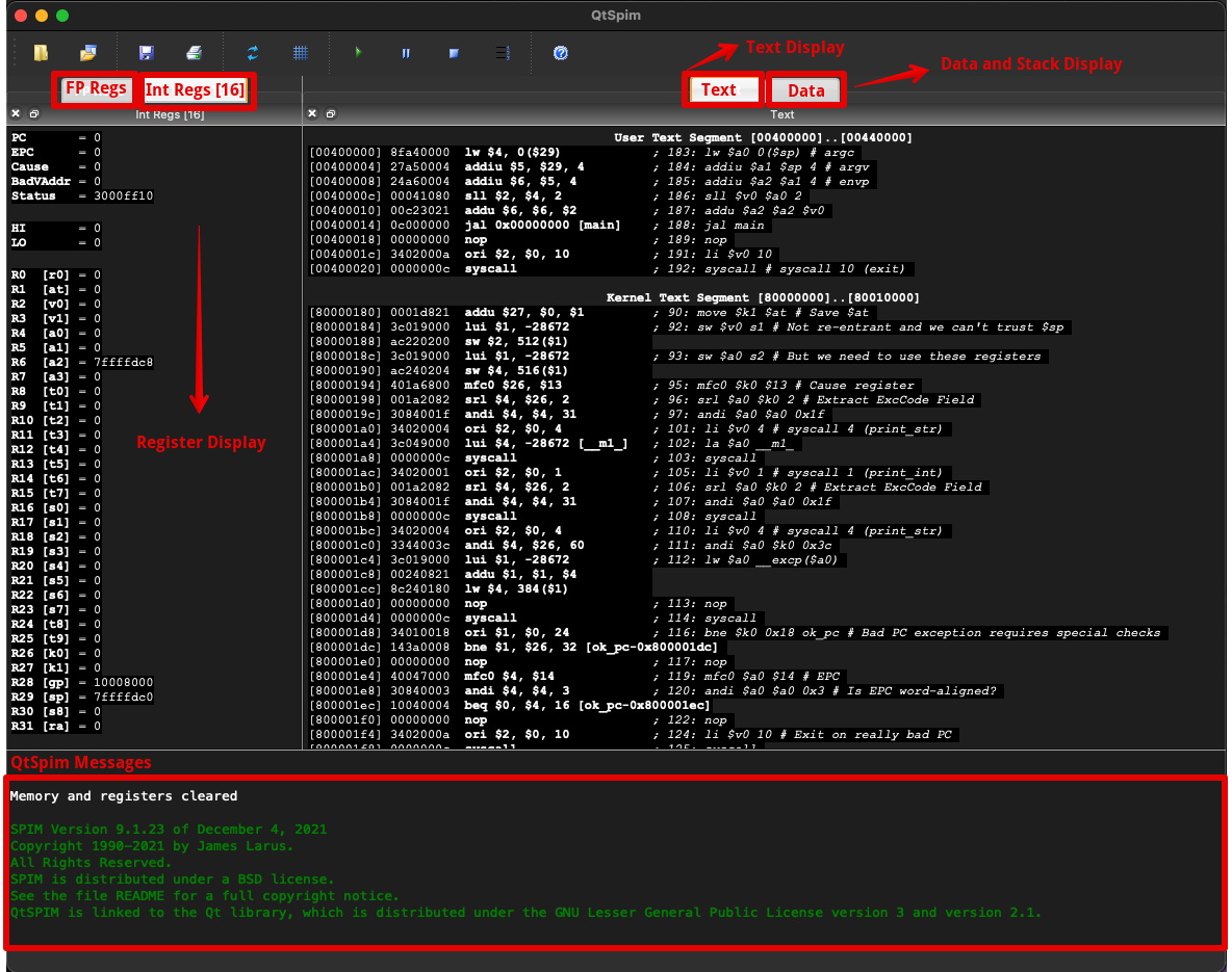
- Register Display: This shows the contents (bit patterns in hex, hence the
Int Regs[16]designation) of all 32 general purpose registers, the floating point registers (i.e., theFP Regs), and a few others. - Text Display: This shows the assembly language program source, the machine instructions (bit patterns in hex) they correspond to, and the addresses of their memory locations.
- Data and Stack Display: This shows the sections of MIPS memory that hold ordinary data and data which has been pushed onto a stack.
- SPIM Messages: This shows messages from the simulator (often error messages).
Text is the name for machine language bit patterns intended for eventual execution. The word "program" is often ambiguous, so "text" is used. "Text" is a machine language program that may be executed by a process.
Character output from the simulated computer is in the SPIM console window.
Question 3
Is there a difference between messages from the simulator and messages from the simulated computer?
Answer
Yes.
Writing an assembly program
Messages from the simulated computer appear in the console window when an assembly program that is running (in simulation) writes to the (simulated) monitor. If a real MIPS computer were running you would see the same messages on a real monitor.
Messages from the simulator are anything the simulator needs to write to the user of the simulator. These are error messages, prompts, and reports.
Now that the simulator is running you need to assemble and load a program. Depending on the settings of the simulator, there already may be some machine instructions in simulated memory. These instructions assist in running your program. If you start the simulator from the Simulator menu this code will run, but it will be caught in an infinite loop. To stop it, click on Simulator; Break.
A source file (in assembly language or in any programming language) is the text file containing programming language statements created (usually) by a human programmer. An editor like Notepad will work. You will probably want to use a better editor, but as a common ground I'll use Notepad. Use whatever editor you use for your usual programming language.
Question 4
(Review) What type of files does Notepad create?
Answer
Text files — files of bytes that can be interpreted as ASCII characters.
Two plus three
Word processors usually create "binary" files and so are not suitable for creating source files. They can be forced to output a text file, but a real programming editor is much nicer. With your program (text) editor create a file called addup.asm. (With most text editors and Web browsers you can copy the following code from the Web page and then paste into the editor).
## Program to add two plus three
        .text
        .globl  main

main:
        ori     $8,$0,0x2       # put two's comp. two into register 8
        ori     $9,$0,0x3       # put two's comp. three into register 9
        addu    $10,$8,$9       # add register 8 and 9, put result in 10

## End of file
The first "#" of the first line is in column one. The character "#" starts a comment; everything on the line from "#" to the right is ignored. Sometimes I use two in a row for emphasis, but only one is needed.
Each of the three lines following main: corresponds to one machine instruction.
Question 5
(Review:) What is a machine instruction?
Answer
A machine instruction is a pattern of bits that asks for one machine operation to be executed.
Setting up SPIM
Each MIPS machine instruction is 32 bits (four bytes) long. The three lines after main: call for three machine instructions. The remaining lines consist of information for the assembler and comments (for the human).
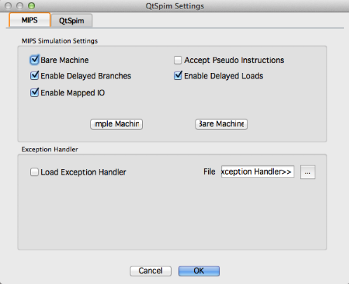
For this first program some SPIM options must be set.
- For Windows, in the menu bar, click on Simulator then Settings to get the settings dialog.
- For Mac, in the menu bar, click on QtSpim then Preferences to get the settings dialog. Select the following options:
| Option | Value |
|---|---|
| Save window positions | ON |
| General registers in hexadecimal | ON |
| Floating point registers in hexadecimal | OFF |
| Bare machine | ON |
| Allow pseudo instructions | OFF |
| Load trap file | OFF |
| Delayed Branches | ON |
| Delayed Load | ON |
| Mapped I/O | ON |
| Quiet | OFF |
These settings simulate a bare machine with no user conveniences. Later we will include the conveniences.
Question 6
(Thought Question) Do most actual computers start up as a bare machine?
Answer
No.
Loading the source file
Modern computers boot up to a user-friendly state. Usually there is some firmware (permanent machine code in EEPROM) in a special section of the address space. This starts running on power-up and loads an operating system. SPIM can simulate some basic firmware, but we have turned off that option.
Load the program into the SPIM simulator by clicking File then Open. Click on the name (addup.asm) of your source file. You may have to navigate through your directories using the file dialog box.
If there are mistakes in addup.asm, SPIM's message display panel shows the error messages. Use your editor to correct the mistakes, save the file then re-open the file in SPIM.
Question 7
Can the text editor and SPIM both be open at the same time?
Answer
tbdAnswer
Assembling the program
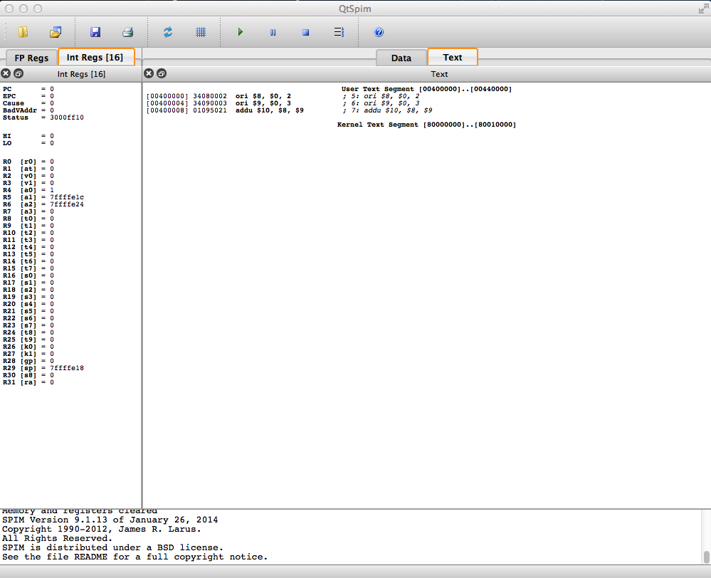
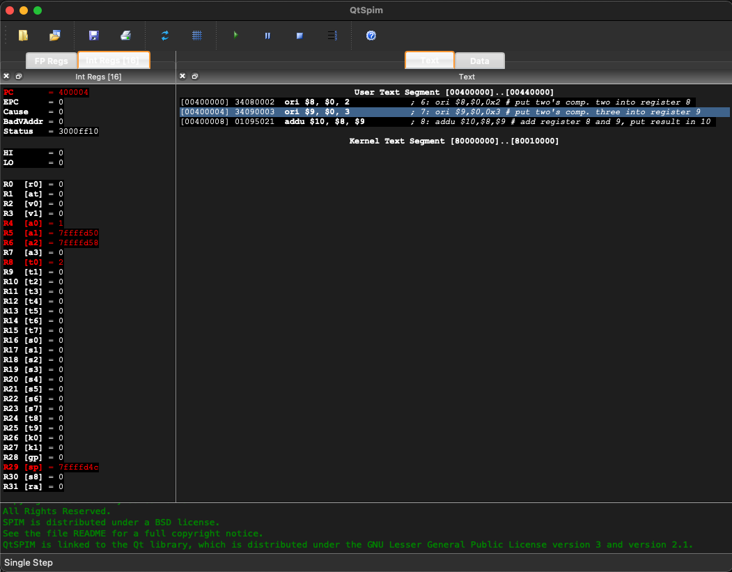
Loading the source file into SPIM does two things: (1) The file is assembled into machine instructions, and (2) the instructions are loaded into SPIM's memory. The text display shows the result.
The text display is the second window from the top. You should see some of the source file in it and the machine instructions they assembled into. The leftmost column are addresses in simulated memory.
Question 8
Inspect the text display (your own or the above picture).
- What machine instruction (bit pattern) did your first instruction (
ori $8,$0,0x2) assemble into? - At what address in memory was it loaded?
Answer
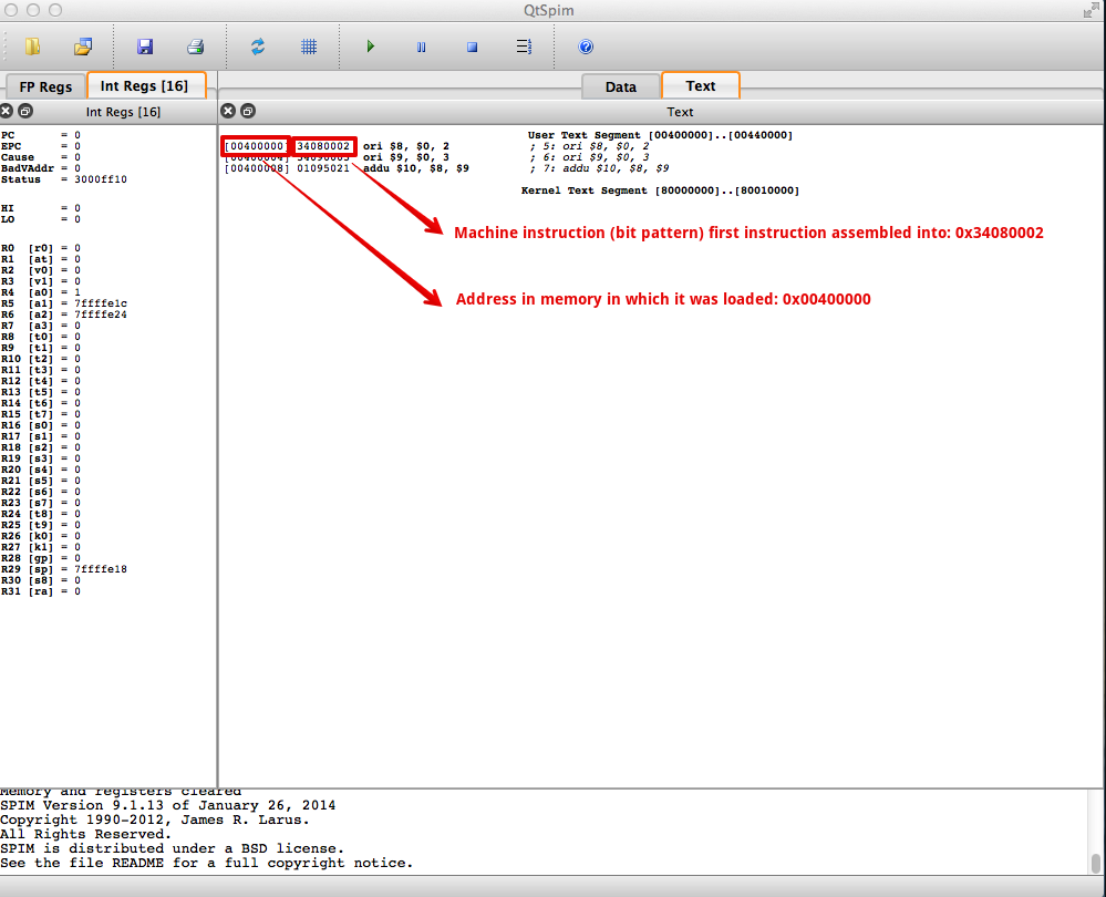
- What machine instruction (bit pattern) did your first instruction assemble into?
0x34080002
- At what address in memory was it loaded?
0x00400000
Setting the PC
The program counter is the part of the processor that contains the address of the current machine instruction. (Actually, it contains the address of the first of the four bytes that make up the current instruction.) In the register display (top window) you see that the PC starts out at zero. This should default to 0x00400000, the address of the first instruction. To change the PC value, select (click on) Simulator; click on Run Parameter; type the address in the top text box. Click on OK and the PC (in the register display) should change.
Question 9
A user types "400000" into the value box, and clicks OK. The PC changes to 00061a80. What happened?
Answer
Without a leading "0x" the characters "400000" are taken to be an integer expressed in decimal. The PC is loaded with the binary representation of that integer.
Running the program
Push F10 to execute one instruction. The first instruction executes, loading register eight with a 2 (see the register display). The PC advances to the next instruction 0x00400004 and the message display window shows the instruction that just executed.
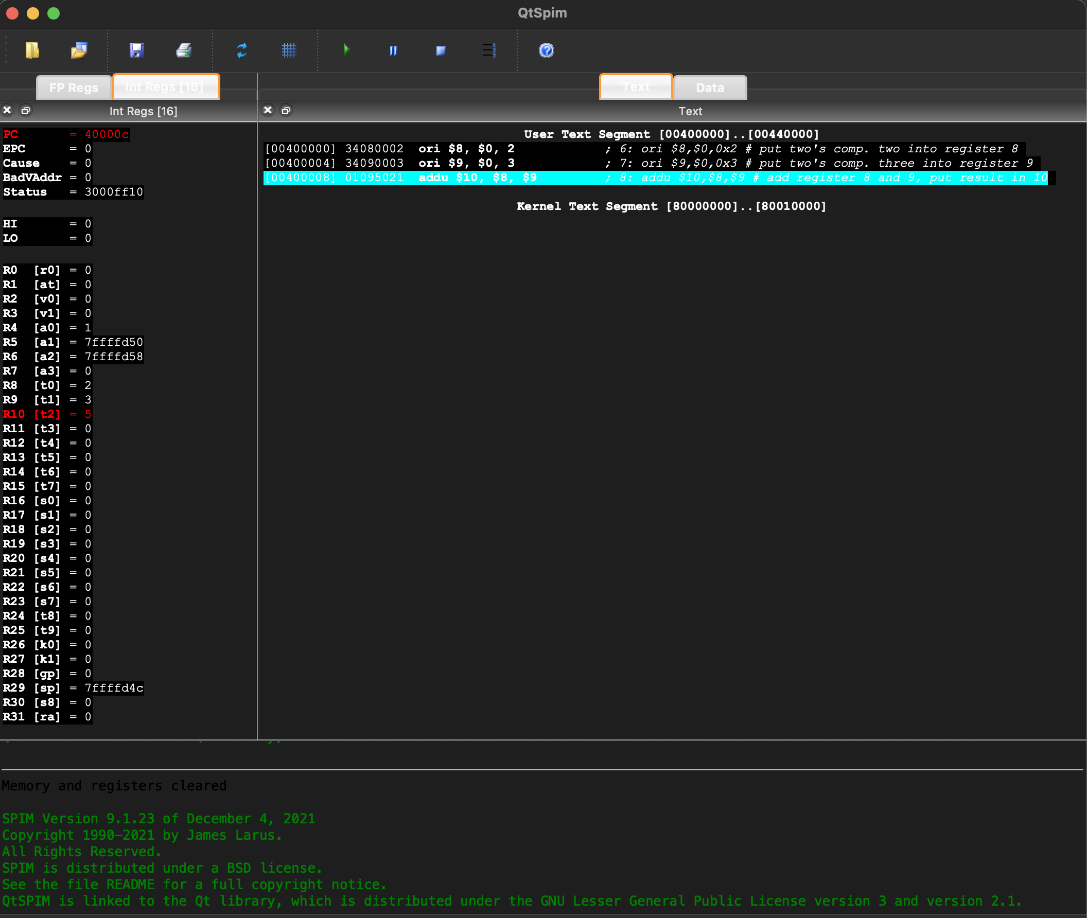
Push F10 two more times to execute the remaining instructions. Each instruction is 32 bits (four bytes) long, so the PC changes by four each time. After the third instruction, register 8 will have the sum of two plus three.
Question 10
What is the sum of 0x0000002 and 0x0000003?
Answer
0x0000005
Program's results
The bit patterns for these small integers are easy to figure out. You may have to use the slider on the register display to see register ten.
If you push F10 again, the PC will point at a word in memory that contains bits not intended to be a machine instruction:
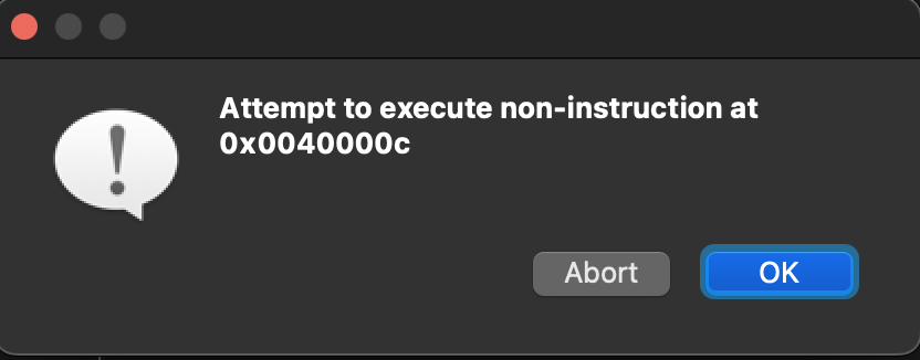
However the simulator will try to execute those bits. A real processor would "crash" at this point. (This is sometimes called "falling off the end of a program"). The simulator prints an error message in the bottom panel.
Question 11
What happens in real computers when the end of a program is reached?
Answer
The program returns control to the operating system.
Explanation of the program
There are various ways for a program executing on a real machine to return control to the operating system. But we have no OS, so for now we will single step instructions. Hopefully you are wondering how the program works. Here it is again:
## Program to add two plus three
        .text
        .globl  main

main:
        ori     $8,$0,0x2       # put two's comp. two into register 8
        ori     $9,$0,0x3       # put two's comp. three into register 9
        addu    $10,$8,$9       # add register 8 and 9, put result in 10

## End of file
The first line of the program is a comment. It is ignored by the assembler and results in no machine instructions.
.text is a directive. A directive is a statement that tells the assembler something about what the programmer wants, but does not itself result in any machine instructions. This directive tells the assembler that the following lines are ".text" — source code for the program.
.globl main is another directive. It says that the identifier main will be used outside of this source file (that is, used "globally") as the label of a particular location in main memory.
Question 12
(Memory test) Where was the first machine instruction placed in memory?
Answer
0x00400000
Explanation continued
Blank lines are ignored. The line main: defines a symbolic address (sometimes called a statement label). A symbolic address is a symbol (an identifier) that is the source code name for a location in memory. In this program, main stands for the address of the first machine instruction (which turns out to be 0x00400000). Using a symbolic address is much easier than using a numerical address. With a symbolic address, the programmer refers to memory locations by name and lets the assembler figure out the numerical address.
## Program to add two plus three
        .text
        .globl  main

main:
        ori     $8,$0,0x2       # put two's comp. two into register 8
        ori     $9,$0,0x3       # put two's comp. three into register 9
        addu    $10,$8,$9       # add register 8 and 9, put result in 10

## End of file
The symbol main is global. This means that several source files can use the symbol main to refer to the same location in storage. (However, SPIM does not use this feature. All our programs will be contained in a single source file.)
Question 13
(Test your intuition: ) Is it likely that several sections of a software system need to refer to each other?
Answer
Yes.
Loading register eight
All software consists of interconnected modules. A connection is made when one module refers to an address in another.
The next line: ori $8,$0,0x2 translates into a 32-bit machine instruction. The machine instruction, upon execution, puts a 32-bit two's complement positive two into register eight (details later).
## Program to add two plus three
        .text
        .globl  main

main:
        ori     $8,$0,0x2       # put two's comp. two into register 8
        ori     $9,$0,0x3       # put two's comp. three into register 9
        addu    $10,$8,$9       # add register 8 and 9, put result in 10

## End of file
The instruction after that translates into a machine instruction that (upon execution) puts a three into register nine. The final instruction translates into a machine instruction that (upon execution) adds register eight to register nine and puts the 32-bit result into register ten.
Question 14
What algorithm do you suppose is used for the 32-bit addition?
Answer
The Binary Addition Algorithm (of Chapter 8)
Run time
It is awkward to keep saying:
The instruction, after it is assembled and loaded into main memory, upon execution does ....
Instead one says:
At run time the instruction does ...
For example,
At run time, the instruction
ori $8,$0,0x2loads register eight with a two.
Even sloppier is,
"the instruction
ori $8,$0,0x2loads register eight with a two."
It is vital that you understand that this phrase is a short way of saying the longer phrase. In a computer it is the bit patterns of machine instructions that cause things to happen, and things happen only at run time.
Sometimes one talks about assembly time, the phase where the assembler is creating bit patterns out of the source file.
Question 15
(Review) In a typical computer system (not a simulated one) where does the assembler place the bit patterns it creates?
Answer
In an object module, stored as a disk file.
With the SPIM simulator the object module step is skipped. The assembler puts the bit patterns directly into (simulated) main memory. To end SPIM, click on File; exit in the menu bar.
Chapter quiz
Question 1
What is a source file?
- (A) a text file that contains statements of programming language.
- (B) a subdirectory that contains programs.
- (C) a file that contains data for a program.
- (D) a document that contains the requirements for a project.
Answer
A
Question 2
What is a register?
- (A) a part of the computer system that keeps track of system parameters.
- (B) a part of the processor that holds a bit pattern.
- (C) a part of the processor that contains its unique serial number.
- (D) the part of the system bus that contains data.
Answer
B
Question 3
What character, in SPIM assembly language, starts a comment?
- (A) #
- (B) $
- (C) //
- (D) *
Answer
A
Question 4
How many bits are there in each MIPS machine instruction?
- (A) 8
- (B) 16
- (C) 32
- (D) Different instructions are diferent lengths.
Answer
C
Question 5
When you open a source file from the File menu of SPIM, what two things happen?
- (A) The file is loaded into memory and execution starts.
- (B) SPIM is booted and the file is opened in the editor.
- (C) The file is assembled into machine instructions, and the machine instructions are loaded into SPIM's memory.
- (D) The program is run and the results are saved to disk.
Answer
C
Question 6
What is the program counter?
- (A) a register that keeps counts the number of errors during execution of a program.
- (B) a part of the processor that contains the address of the first word of data.
- (C) a variable in the assembler that numbers the lines of the source file.
- (D) a part of the processor that contains the address of the next machine instruction to be fetched.
Answer
D
Question 7
Say that you push F10 to execute one instruction. What amount is added to the program counter?
- (A) 1
- (B) 2
- (C) 4
- (D) 8
Answer
C
Question 8
What is a directive, such as the directive .text?
- (A) an assembly language statement that results in one machine language instruction.
- (B) one of the menu choices in the SPIM menu system.
- (C) a machine language instruction that causes an operation on data.
- (D) a statement that tells the assembler something about what the programmer wants, but does not itself directly correspond to a machine
Answer
D
Question 9
What is a symbolic address?
- (A) a location in memory containing symbolic data.
- (B) a byte in memory that holds the address of data.
- (C) the symbol given as the argument for a directive.
- (D) a name used in assembly language source code for a location in memory.
Answer
D
Question 10
At what address does the SPIM simulator put the first machine instruction when it is running with the Bare Machine option turned ON?
- (A) 0x00000000
- (B) 0x00400000
- (C) 0x10000000
- (D) 0xFFFFFFFF
Answer
B
MIPS Programming Model
This chapter presents a programming model for the MIPS processor. A programming model is an abstract view of a processor that is appropriate for programming but omits details that are not needed for that task. It is the view of the machine a programmer uses when programming.
Chapter Topics:
- Basic MIPS Programming model
- Memory
- Registers
- Machine cycle
- Control flow
Question 1
As you drive down the highway, are you constantly thinking about the ignition coil of your car?
Answer
No — you use a "drivers view" of the car which is appropriate for driving and omits details not needed for that task. Of course you don't always use that view. If it starts raining and your car starts sputtering you might start thinking about the coil.
Memory model

Modern computer systems nearly always use cache memory and virtual memory. But our abstract view of memory does not include them. The purpose of virtual memory is to make it appear as if a program has the full address space available. So our programming model has the full address space. The purpose of cache is to transparently speed up memory access. So our programming model does not include cache. Memory in the programming model is as follows:
DATA:
MIPS memory is an array of bytes. Each byte has a 32-bit address. Each byte can hold an 8-bit pattern, one of the 256 possible 8-bit patterns. The addresses of MIPS main memory range from 0x00000000 to 0xFFFFFFFF.
However, user programs and data are restricted to the first 231 bytes. The last half of the address space is used for the operating system and for specialized purposes.
OPERATIONS:
The processor chip contains registers, which are electronic components that can store bit patterns. The processor interacts with memory by moving bit patterns between memory and its registers.
- Load: a bit pattern starting at a designated address in memory is copied into a register inside the processor.
- Store: a bit pattern is copied from a processor register to memory at a designated address.
Bit patterns are copied between the memory and the processor in groups of one, two, four, or eight contiguous bytes. When several bytes of memory are used in an operation, only the address of the first byte of the group is specified.
Question 2
- Does a load operation change the bit pattern in memory?
- Does a store operation change the bit pattern in memory?
Answer
- NO: a copy of memory is made in a register.
- YES: the bit pattern in the register replaces the contents of the designated addresses.
Memory layout
Load and store operations copy the bit pattern from the source into the destination. The source (register or memory) does not change. Of course, the pattern at the destination is replaced by the pattern at the source.
Memory is built to store bit patterns. Both instructions and data are bit patterns, and either of these can be stored anywhere in memory (at least, so far as the hardware is concerned.) However, it is convenient for programmers and systems software to organize memory so that instructions and data are separated. At right is the way MIPS operating systems often lay out memory.
Although the address space is 32 bits, the top addresses from 0x80000000 to 0xFFFFFFFF are not available to user programs. They are used for the operating system and for ROM. When a MIPS chip is used in an embedded controller the control program exists in ROM in this upper half of the address space.
The parts of address space accessible to a user program are divided as follows:
- Text Segment: This holds the machine language of the user program (the text).
- Data Segment: This holds the data that the program operates on. Part of the data is static. This is data that is allocated by the assembler and whose size does not change as a program executes. Values in it do change; "static" means the size in bytes does not change during execution. On top of the static data is the dynamic data. This is data that is allocated and deallocated as the program executes. In C programming, dynamic allocation and deallocation is done with
malloc()andfree(). - Stack Segment: At the top of user address space is the stack. With high level languages, local variables and parameters are pushed and popped on the stack as procedures are activated and deactivated.
Question 3
(Thought Question) As the program runs, the data segment grows upward (as dynamic variables are allocated) and the stack grows downward (as procedures get called). Is this sensible? (Hint: how much user memory is left when the two segments meet?)
Answer
Yes. Rather than allocate a fixed amount of memory for each, this arrangement means each can grow into available memory. When the two meet, there is no memory left.
Registers
Often data consist of several contiguous bytes. Each computer manufacturer has its own idea of what to call groupings larger than a byte. The following is used for MIPS chips.
- byte: eight bits (8 bits)
- word: four bytes (32 bits)
- double word: eight bytes (64 bits)
A block of contiguous memory is referred to by the address of its first byte (ie. the byte with the lowest address.) Most MIPS instructions involve a fixed number of bytes.
Often you need a number of bits other than one of the standard amounts. Use the next larger standard amount, and remember to be careful. Attempting to use the very minimum number of bits is more complicated than it is worth and is a rich source of errors in assembly language programming.
A register is a part of the processor that can hold a bit pattern. On the MIPS, a register holds 32 bits. There are many registers in the processor, but only some of them are visible in assembly language. The others are used by the processor in carrying out its operations.
- A load operation copies a bit pattern from memory into a register.
- A store operation copies a bit pattern from a register into memory.
The registers that are visible in assembly language are called general purpose registers and floating point registers. There are 32 general purpose registers. Each general purpose register holds a 32 bit pattern. In assembly language, these registers are named $0, $1, $2, ... , $31. There are 32 floating point registers. These are discussed in a later chapter.
One of the general purpose registers is hard-wired to always contain the value 0x00000000 (all zero bits).
Question 4
Which register $0, $1, $2, ... , $31 do you suppose always contains all zero bits?
Answer
$0
The bit pattern 0x00000000 occurs so frequently in machine language that register $0 is wired to permanently hold it. That bit pattern represents the integer zero, a very common integer. It also represents a null, which is used to mark the end of character strings and often used in building data structures.
Registers and the ALU
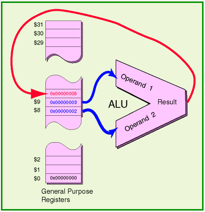
The arithmetic/logic unit (ALU) of a processor performs integer arithmetic and logical operations. For example, one of its operations is to add two 32-bit integers. An integer used as input to an operation is called an operand. One operand for the ALU is always contained in a register. The other operand may be in a register or may be part of the machine instruction itself. The result of the operation is put into a general purpose register.
Machine instructions that use the ALU specify four things:
- The operation to perform.
- The the first operand (often in a register).
- The second operand (often in a register).
- The register that receives the result.
The picture shows a 32-bit addition operation. The operands come from register $8 and from register $9. The result is put in register $10. Here is how that instruction is written as assembly language:
addu $10,$8,$9
Question 5
Here is another instruction that involves the ALU, written as assembly language:
subu $25,$16,$17
Identify the following:
- The operation:
___ - The location of one operand:
___ - The location of the other operand:
___ - The destination of the result:
___
Answer
- The operation:
subtraction of two 32-bit integers - The location of one operand:
register $16 - The location of the other operand:
register $17 - The destination of the result:
register $25
At run time: Register $25 is set to (Register $16) - (Register $17)
Machine code
On some processors (such as the VAX) the ALU can operate directly on data contained in main memory. However, this requires extra data paths and control logic and slows down execution. On the MIPS, operands for the ALU and the destination for the result are inside the chip (usually registers).
Here is the assembly language for the add instruction:
addu $10,$8,$9
Here is the machine code it translates into:
0x01095021
Here is that as a bit pattern:
0000 0001 0000 1001 0101 0000 0010 0001
Here is the bit pattern arranged into different groups. Under each group is what the pattern means as a machine instruction. (A group of bits that is part of a larger bit pattern is often called a field). Each field of a machine instruction has a specific function.
Inspect the groups until you see how the instruction specifies the four things: (1) the operation, (2) operand 1, (3) operand 2, (4) destination of the result.
A machine instruction consists of fields that specify a machine operation and other fields that designate the data. The 12 bits that specify the addu operation are split into two groups. The first group is called the opcode and the second group is called the secondary opcode.
The register numbers are readable as binary integers. Some bits of the instruction are left as zero. You have to look at MIPS documentation to figure all this out.
Question 6
Here is the machine instruction again, but the pattern that specifies the destination is blank. Fill it in so the destination is register $11.
000000 01000  01001 _ _ _ _ _ 00000 100001

ALUop   $8    $9    $11             addu
       op1   op2    dest
Answer
000000 01000  01001 0 1 0 1 1 00000 100001

ALUop   $8    $9    $11             addu
       op1   op2    dest
Register use conventions
| Register number | Mnemonic name | Conventional use |
|---|---|---|
$0 | zero | Permanently 0 |
$1 | $at | Assembler temporary (reserved) |
$2, $3 | $v0, $v1 | Value returned by a subroutine |
$4-$7 | $a0-$a3 | Arguments to a subroutine |
$8-$15 | $t0-$t7 | Temporary (not preserved across a function call) |
$16-$23 | $s0-$s7 | Saved registers (preserved across a function call) |
$24, $25 | $t8, $t9 | Temporary |
$26, $27 | $k0, $k1 | Kernel (reserved for OS) |
$28 | $gp | Global pointer |
$29 | $sp | Stack pointer |
$30 | $fp | Frame pointer |
$31 | $ra | Return address (automatically used in some instructions) |
Congratulations! (if you correctly answered the question). You have just done some machine language programming. Who needs that old assembler, anyway?
General purpose registers are those that assembly language programs work with (other than floating point registers). The general purpose registers are numbered $0 through $31. However, by convention (and sometimes by hardware) different registers are used for different purposes.
In addition to a number $0 through $31, registers have a mnemonic name (a name that reminds you of its use). For example register $0 has the mnemonic name zero. The table shows the 32 registers and their conventional use.
Registers $0 and $31 are the only two that behave differently from the others. Register $0 is permanently wired to contain zero bits. Register $31 is automatically used by some subroutine linkage instructions to hold the return address.
If this looks totally cryptic, don't worry. Don't try to memorize this. You will get used to what you need to know after writing a few programs.
Question 7
A program has just calculated an important value which is contained in register $8. It copies this value to register $0. Is this wise?
Answer
No, because register $0 always contains a zero. You may try to copy a value into it, and the instruction will appear to execute correctly, but register zero will not be changed.
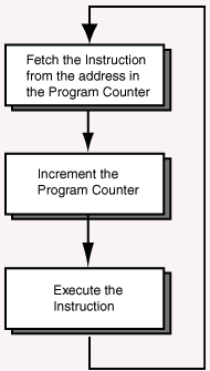
Model machine cycle
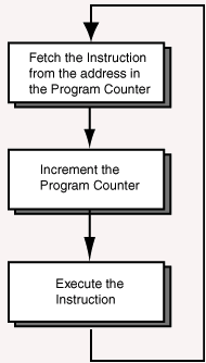
The MIPS assembly programming model includes a machine cycle (repeated here from chapter one). The MIPS endlessly cycles through three basic steps. Each cycle executes one machine instruction. Everything the processor does is done by a sequence of machine operations. So, everything that a program does is the result of performing millions of machine cycles.
As execution proceeds through a list of instructions, a special register, the program counter, points at the instruction that is next in line to execute.
- Fetch the next Instruction. The program counter contains the address of the next machine instruction. The instruction is fetched from memory.
- Increment the PC. The address in the program counter is incremented by four.
- Execute the Instruction. The machine operation specified by the instruction is performed.
Question 8
Why is the program counter (PC) incremented by four each time?
Answer
Each MIPS instruction is 32 bits (four bytes) long. The PC is incremented to point at the next instruction.
Sequential execution
MIPS machine instructions are all 32 bits wide (4 bytes). Normally, instructions are executed one after another starting with the first instruction of the program and proceeding upward through memory. The execution sequence can be changed with a branch or a jump machine instruction.
Here, for example, is the program from the previous chapter. The three machine instructions have been placed at locations 0x00400000, 0x00400004, and 0x00400008, and are executed in that order.
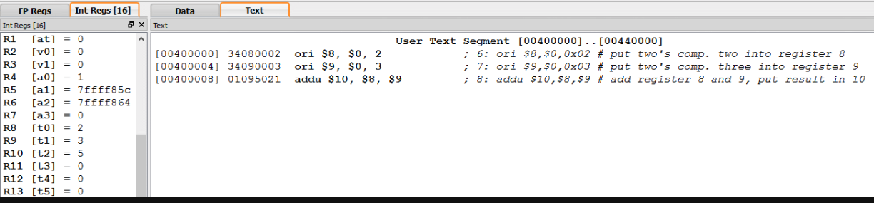
It would take three machine cycles to execute this very tiny program.
Question 9
After the instruction at 0x00400008 has executed, what happens?
Answer
The processor fetches the 32-bit pattern (whatever it is) at address 0x0040000C and tries to execute it as an instruction.
(Actually, the SPIM simulator stops at this point. This is a convenience for student programmers, but not what actual hardware would do.)
Control
Any bit pattern that is fetched as an instruction by the machine cycle is interpreted as an instruction. The bit patterns in the fields tell the electronics what operation to perform and what data to use. If the bit pattern makes no sense as an instruction then the machine cycle is interrupted. This causes the program to "crash" (or to "bomb".) However, if the pattern can be interpreted as an instruction then it will be executed, whatever it does.
The control point of an executing program is the address in memory of the instruction being executed. When an instruction is being executed (in the third step of the machine cycle) the program counter holds the address of the instruction after the control point.
Normally the control point moves sequentially through the machine instructions. On the MIPS this means it normally moves through memory in steps of four bytes (32 bits) at a time. Usually "control point" is shortened to "control" and the phrase flow of control means how the control point moves through memory.
If control flow leads to an address in memory, then the four bytes starting at that address are fetched as a machine instruction. The processor has no other way to tell instructions from data. Whatever bit pattern gets pulled in from memory as an instruction will be executed as an instruction. It is common for the control point of a buggy program to enter a section of data. Now, bit patterns that were intended as data get executed as instructions. This sometimes leads to mystifying results.
By software convention, data and instructions are placed in different sections of memory. (This helps prevent mystifying results). But this is not a requirement of the architecture.
Some processors have bounds registers that the operating system sets to the first and last address of a user program. Only instructions within bounds may be fetched as instructions. This also helps prevent mystification.
Question 10
Most computer systems start running an operating systems when power is applied. When an application program runs, the operating system passes control to the application.
What must the application do when it is finished running?
Answer
Pass control back to the operating system.
Multitasking
With Microsoft's DOS, programs were passed control, ran until completion, then passed control back to DOS. So only one application ran at a time. Worse, an application that messed up might never return control to DOS and the whole system would freeze.
Modern computer systems include features that can interrupt the control flow of an executing program. After the flow is interrupted, the operating system can give control to another application. If this is done many times a second the computer system appears to be simultaneously executing several applications. This trick is called multitasking. It has been used from about 1960 for mainframes, from 1978 for many microcomputers, and from about 1995 for Windows PCs.
The MIPS chip has very good support for multitasking. But this is an advanced topic not included in our basic programming model.
Question 11
Do human brains do multitasking?
Answer
Human brains work (mostly) in parallel. Multitasking gives the appearance of parallel processing. Brains and some computers actually do it.
Model summary
Here is a summary of the basic MIPS programming model.
- Machine Instructions: Machine instructions are thirty-two bits wide. Bit patterns specify the operation, the operands, and the destination for the result. Basic operations are arithmetic, logic, memory access, and control branches.
- Machine Cycle: The machine cycle is illustrated above. Execution proceeds sequentially one instruction at a time. The control point indicates the instruction about to execute. ALU operations never directly access memory.
- Registers: Thirty-two 32-bit wide general purpose registers, which have various conventional uses. Register
$0is hard-wired to 32 zero-bits. - Memory: Thirty-two bit address space, but only the lower half (most of it anyway) is for user programs. User memory is further divided (by software convention) into text, data, and stack segments.
Chapter quiz
Question 1
When a register is loaded what happens?
- (A) The bits of the register are set to all ones.
- (B) The bit pattern in the register is copied to a location in memory.
- (C) A bit pattern at a memory location is copied to the register. The memory is set to all zeros.
- (D) A bit pattern at a memory location is copied to the register. Memory is not changed.
Answer
D
Question 2
When a register is stored what happens?
- (A) The bits of the register are set to all ones.
- (B) The bit pattern in the register is copied to a location in memory.
- (C) A bit pattern at a memory location is copied to the register. The memory is set to all zeros.
- (D) A bit pattern at a memory location is copied to the register. Memory is not changed.
Answer
B
Question 3
By software convention, the machine instructions of a program are put in a designated section of memory. What is this section called?
- (A) Data segment.
- (B) Stack segment.
- (C) Program segment.
- (D) Text segment.
Answer
D
Question 4
What general purpose register is permanently set to thirty-two zero bits?
- (A)
$0 - (B)
$1 - (C)
$31 - (D)
$32
Answer
A
Question 5
What part of the processor chip performs arithmetic and logical operations?
- (A) CPU
- (B) ALU
- (C) ROM
- (D) PCI
Answer
B
Question 6
Where do the operands for an arithmetic machine instruction come from?
- (A) Both operands are registers.
- (B) Both operands come from memory.
- (C) One operands must be a register, the other one may be memory or a register.
- (D) One operand must be a register, the other may be a register or may be part of the machine instruction.
Answer
D
Question 7
What is an opcode?
- (A) The part of a machine instruction that designates the data to be used.
- (B) A bit field, part of a machine instruction, that designates a machine operation.
- (C) The part of the processor chip that performs decoding operations.
- (D) The part of a machine instruction that is used as data in an operation.
Answer
B
Question 8
There are 32 general purpose registers. So a machine instruction must use a bit field of what size to designate a register?
- (A) 3
- (B) 4
- (C) 5
- (D) 16
Answer
C
Question 9
What is the mnemonic name of a register?
- (A) A register number like
$0or$31. - (B) A name that helps you remember the hardware characteristics of the register.
- (C) The bit pattern that designates the register in a machine instruction.
- (D) A name like
$s0that helps you remember the conventional software uses for the register.
Answer
D
Question 10
What, in order, are the three steps of the machine cycle?
- (A) fetch, increment, execute.
- (B) Execute, fetch, increment.
- (C) Fetch, exectue, increment.
- (D) increment, fetch, execute.
Answer
A
Bitwise Logic with Immediate Operands
Some machine instructions contain data as part of the instruction. This data is an immediate operand. The ori instruction used in the previous chapter contains an immediate operand.
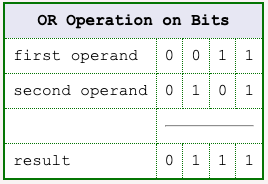
With a bitwise logic operation two bit patterns are "lined up" and then an operation such as OR or AND is performed between pairs of bits.
Chapter Topics:
- Immediate Operands.
- Bitwise Logic.
- Bitwise OR, AND, and XOR
- Format of Machine Instructions.
- Zero Extension of a Bit Pattern.
- OR Immediate with $0 as a Load Instruction.
Question 1
Could a 32-bit MIPS instruction have room for a 16-bit two's complement integer?
Answer
Yes, as long as the remaining bits are enough to specify the operation.
Immediate operand
Some machine instructions use 16 of their 32 bits to hold one of the two operands. An operand that is directly encoded as part of a machine instruction is called an immediate operand. For example, here is one of the instructions from the previous example program:
address         machine code      assembly code

0x00400000      0x34080002        ori $8,$0,0x2
                      ----
The last 16 bits (four hex characters) of the machine instruction contain the operand 0x0002. (The assembly language instruction can just say "0x2"). The machine instruction tells the ALU to perform a bitwise OR between the contents of register $0 and the immediate operand 0x0002. The result is put in register $8.
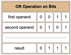
A bitwise operation is where a logical operation is performed on the bits of each column of the operands. Here is the bitwise OR between two 8-bit patterns:
0110 1100    operand
0101 0110    operand
---------
0111 1110    result
Question 2
- What bit pattern is contained in register
$0? - How many bits are there in each MIPS instruction?
Answer
- What bit pattern is contained in register
$0?- All zero bits
- How many bits are there in each MIPS instruction?
- 32 bits
Zero extension
Look again at the instruction:
address         machine code      assembly code

0x00400000      0x34080002        ori $8,$0,0x2
                      ----
Sixteen bits of immediate operand,
0000 0000 0000 0010
are to be bitwise ORed with the thirty-two bits of register zero,
0000 0000 0000 0000 0000 0000 0000 0000
This would not ordinarily be possible because the operands are different lengths. However, MIPS zero extends the sixteen-bit operand so the operands are the same length. Sometimes this is called padding with zeros on the left.
   zero extension
---- ---- ---- ----
0000 0000 0000 0000 0000 0000 0000 0010   -- zero extended immediate operand
0000 0000 0000 0000 0000 0000 0000 0000   -- data in register $0
---------------------------------------
0000 0000 0000 0000 0000 0000 0000 0010   -- result, put in register $8
An OR operation is done in each column. The 32-bit result is placed in register $8.
Question 3
After the instruction ori $8,$0,0x2 executes, what is in $8?
Answer
The 16-bit 0x2 immediate operand has been zero-extended and copied into register $8.
OR immediate instruction
Because the OR operation was done with the zeros in register $0, the result was a copy of the zero-extended immediate operand. Copying a bit pattern into a register is usually called loading the register. Register $8 was loaded with a 32-bit pattern. The pattern could represent a positive two. If so, register $8 was loaded with positive two. Here is a description of the ori instruction when used to load a register:
ori  d,$0,const    # register d <-- const.
                   # const is 16-bits, so
                   # 0x0000 ... const ... 0xFFFF
If const represents an integer, then 0 ≤ const ≤ 65535. The three operands of the assembly instruction d, $0, and const must appear in that order.
Question 4
Can the immediate operand of an ori be regarded as a signed integer?
Answer
No. Because the 16-bit pattern is zero-extended to 32 bits, the resulting pattern is never a two's-complement negative integer.
General OR immediate instruction
Here is a description of the ori instruction used as a bitwise OR instruction:
ori  d,s,const     # register d <-- bitwise OR of const
                   #                with the contents of register $s
                   #                const is 16-bits, so
                   #                0x0000 ... const ... 0xFFFF
The parts of the instruction must appear in the correct order, and const must be within the specified range. If the immediate operand in the assembly language shows less than 16 bits (as does 0x2 in the previous example) then the assembler expands it to the required sixteen bits. If the assembly language specifies more than sixteen bits, then the assembler writes an error message.
The const part of the assembly language instruction can be a positive decimal or a hexadecimal constant. The assembler translates the constant into a 16-bit pattern in the machine instruction. For example, the following two assembly language instructions translate into the same machine language instruction:
ori  $5,$4,0x10
ori  $5,$4,16
Question 5
Is the following instruction correct?
ori $0,$9,0x32
Answer
Incorrect. It says to put the result into register $0 (which is always zero and can't be loaded with anything else).
Example
The assembler part of the SPIM simulator does not write an error message for the above mistaken instruction. But the instruction does not change register zero when executed.
Here is a tiny program that bitwise ORs two patterns. First one pattern is loaded into register $8, then the register is ORed with an immediate operand. The result goes into register $10.
## Program to bitwise OR two patterns
        .text
        .globl  main

main:
        ori      $8,$0,0x0FA5       # put first pattern into register $8
        ori     $10,$8,0x368F       # or ($8) with second pattern.  Result to $10.

## End of file
Soon we will assemble and run the program. You can do this now, if you want (remember you can use copy-and-paste from this page to your text editor). First, let us predict the result.
Question 6
Here are the two patterns, written both in bit patterns and in hex. Perform the bitwise OR operation. (Do it with the bits, then re-write the answer in hex).
0000 1111 1010 0101           0FA5
0011 0110 1000 1111           368F
Answer
0000 1111 1010 0101           0FA5
0011 0110 1000 1111           368F
-------------------           ----
0011 1111 1010 1111           3FAF
Running the program
Doing the problem by hand yields the result, 0x3faf. Of course, when the program runs the result will be 32 bits long: 0x00003faf. To run the program:
- Create a source file.
- Start SPIM.
- Load the source file.
- Set simulator switches (only the following matter at this time):
- ON — general registers in hexadecimal.
- ON — bare machine.
- OFF — allow pseudo instructions.
- OFF — load trap file.
- Push F10 once per instruction.
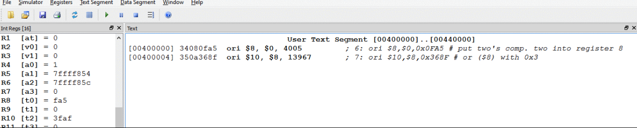
The picture shows the result of running the program. The result in $10 is what was expected.
Question 7
Here is the complete line for the first instruction from the source window:
[0x00400000] 0x34080fa5 ori $8, $0, 4005 ori $8,$0,0x0FA5
Look at the 32-bit machine instruction at address 0x00400000. Do you see the immediate operand in it?
(Recall that the SPIM window shows the dis-assembly of the machine code, which in the above is ori $8, $0, 4005. The disassembly uses base 10 to show the bit pattern as if it were representing an integer.)
Answer
[0x00400000]    0x34080fa5      ori  $8, $0, 4005     ori  $8,$0,0x0FA5
                      ----                                         ----
Yes. How could you miss? The last 16 bits are the immediate operand.
ORI machine code
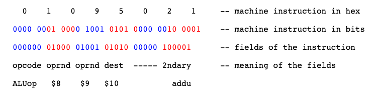
Below is the machine code for the instruction. In the third line the bits have been grouped into fields that have various functions. Documentation for the MIPS shows the fields for each instruction. It is not something you could determine by inspection.
Look this over to get an idea of how it works. The left six bits of the instruction are the opcode, the bit pattern that specifies the machine operation. The next group of five bits specifies the operand register. The group of five after that specifies the destination register. The remaining bits are the immediate operand.
   3    4    0    8    0    f    a    5    -- machine instruction in hex

0011 0100 0000 1000 0000 1111 1010 0101    -- machine instruction in bits

001101  00000 01000 0000 1111 1010 0101    -- fields of the instruction

ori     $0     $8     0    f    a    5
opcode  oper-  dest  immediate operand     -- meaning of the fields
        and    reg.
        reg.

ori     $8,  $0,  0x0fa5                   -- assembly language instruction
                                              (Notice that the register numbers
                                               are not in the same order as they
                                               are in the machine instruction).
Question 8
Here is the ori instruction again, but the patterns that specify the operand register, the destination register, and the immediate operand are blank. Fill in the blanks so the operand register is $10, the destination register is $9 , and the immediate operand is 0xAFF0.
001101 _ _ _ _ _   _ _ _ _ _  _ _ _ _  _ _ _ _  _ _ _ _  _ _ _ _

ori     $10          $9         a         f        f        0

     operand        dest           immediate operand
     reg.           reg.
Answer
       0 1 0 1 0  0 1 0 0 1  1 0 1 0  1 1 1 1  1 1 1 1  0 0 0 0
001101 _ _ _ _ _  _ _ _ _ _  _ _ _ _  _ _ _ _  _ _ _ _  _ _ _ _

ori     $10          $9         a         f        f        0

       operand      dest           immediate operand
       reg.         reg.
Machine instructions compared
Here again is the ori machine instruction:
   3    4    0    8    0    f    a    5    -- machine instruction in hex

001101  00000 01000 0000 1111 1010 0101    -- fields of the instruction

opcode  oper  dest  immediate operand      -- meaning of the fields
        -and  reg.
        reg.

ori     $0      $8     0    f    a    5
The layout of this machine instruction is different from the addu instruction we looked at in chapter 10:
   0    1    0    9    5    0    2    1    -- machine instruction in hex

000000 01000 01001 01010 00000 100001      -- fields of the instruction

opcode oprnd oprnd dest  ----- 2ndary      -- meaning of the fields

ALUop   $8    $9   $10           addu
Both instructions are 32 bits wide (as are all MIPS32 instructions). The first six bits are the opcode, which calls for an ALU operation. The addu instruction further specifies the operation in the last six bits, the secondary opcode. The addu instruction does not have an immediate operand.
Question 9
Do the fields of two different machine instructions necessarily have the same size and same meaning?
Answer
No.
Use of bitwise logic
The first six bits of a machine instruction (the opcode) specify the machine operation. (Sometimes a secondary opcode is needed). The opcode also determines how the rest of the instruction is laid out. A human needs to look at documentation to figure out the bit fields of an instruction and what they mean. The MIPS processor does this automatically.
Recall (from the second chapter) the fourth advantage of binary:
- Simple; easy to build.
- Unambiguous signals (hence noise immunity).
- Flawless copies can be made.
- Anything that can be represented with some sort of pattern can be represented with patterns of bits.
Most computers have built-in integer arithmetic operations and often built-in floating point operations. But computers are used for much more than numbers! Bit patterns are used to represent very many things. Bitwise logic is needed when computing with bit patterns in all their various uses.
For example, a document created with a word processor has font and formatting information embedded within it. The information is encoded with bit patterns in ways specific to each word processor family. A word processor program must use bitwise operations to process these codes.
Question 10
What type of program reads in strings of symbols encoded in ascii and outputs bit patterns that encode data and machine operations?
Answer
An assembler.
Handy ANDI instruction
An assembler uses bit manipulation to put together (to "assemble") the bit patterns of each machine instruction. This is a typical assignment in a systems programming course. Of course, you will likely write your assembler in C and will use its bitwise operators. But they ultimately become the processor's bitwise operations.
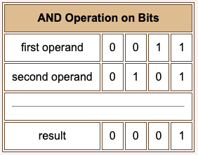
The andi instruction does a bitwise AND of two 32-bit patterns. At run time the 16-bit immediate operand is padded on the left with zero bits to make it a 32-bit operand.
andi d,s,const     # register d loaded with
                   # bitwise AND of immediate operand const
                   # and the contents of register $s.
                   # const is a 16-bit pattern, so
                   # 0x0000 ... const ... 0xFFFF
The three operands of the instruction must appear in the correct order, and const must be within the specified range. The immediate operand in the source instruction always specifies sixteen bits although the zeros on the left can be omitted (such as 0x2).
Question 11
Is the following instruction correct? What does it do?
andi $8,$0,0xFFFF
Answer
It is correct, but not very sensible. It ANDs the contents of the zero register (all zeros) with the immediate operand and puts the result in register $8. Of course, the result is all zeros, regardless of the immediate operand.
Exclusive OR immediate
Filling a register with all zero bits is called clearing the register. Clearing a register is common, but the above instruction is not the best way to do it.
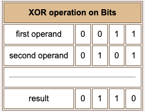
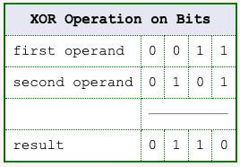
An exclusive OR is nearly the same as the more common OR (the inclusive OR) except that the result is zero when both operands are one.
Here is a description of the assembly language instruction. The machine language for the instruction looks much the same as the ori and the andi instruction.
xori d,s,const     # register d is assigned
                   # the bitwise XOR of immediate
                   # operand const
                   # and the contents of register $s.
                   # const is a 16-bit pattern, so
                   # 0x0000 ... const ... 0xFFFF
The three operands of the instruction must appear in the correct order, and const must be within the specified range. If the immediate operand in the assembly program is less than sixteen bits (such as 0x2) the assembler expands it to sixteen. If it is more than sixteen bits the assembler writes an error message.
Question 12
Here are the two patterns, written both in bit patterns and in hex. Perform the bitwise XOR operation. (Do it with the bits, then re-write the answer in hex).
0000 1111 1010 0101       0FA5
0011 0110 1000 1111       368F
------------------------------
Answer
0000 1111 1010 0101       0FA5
0011 0110 1000 1111       368F

0011 1001 0010 1010       392A
Example program
Here is a program that does all three bitwise operations between the same two patterns. The destination register is different in each case.
## Program to bitwise OR, AND, and XOR two patterns
        .text
        .globl  main

main:
        ori     $15, $0,0x0FA5       # put bit pattern register into $15
        ori      $8,$15,0x368F       # OR with second pattern
        andi     $9,$15,0x368F       # AND with second pattern
        xori    $10,$15,0x368F       # XOR with second pattern

## End of file
Running it in SPIM (pushing F10 four times) results in the following:
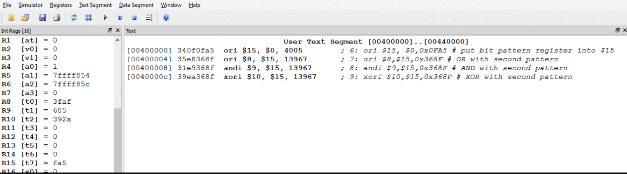
The register display on the left shows the results of the three logic operations. Select "Hex" from the "Registers" menu to see register content displayed using hexadecimal pattern names. The registers always hold 32 bits (of course), but the display does not show leading zeros. So the result of the xori operation given in the answer (see above) is displayed as
392a
corresponding to what is really in the register
0000392a hexadecimal for 0000 0000 0000 0000 0011 1001 0010 1010
Question 13
What is the exclusive-OR of a bit pattern with itself? Try this with a few bit patterns written on a scrap of paper.
Answer
The result is all zero-bits.
An exclusive OR of a bit pattern with itself results in all zeros.
Because the two operands are identical, only two XOR operations are involved: 0 XOR 0 = 0 and 1 XOR 1 = 0.
Chapter quiz
Question 1
Some machine instructions contain one of the operands for the operation they specify. What is such an operand called?
- (A) immediate operand
- (B) embedded operand
- (C) binary operand
- (D) machine operand
Answer
A
Question 2
What is it called when a logical operation is performed between the bits of each column of the operands to produce a result bit for each column?
- (A) logic operation
- (B) bitwise operation
- (C) binary operation
- (D) column
Answer
B
Question 3
When an operation is actually performed, what is true of the operands in the ALU?
- (A) At least one operand must be 32 bits wide.
- (B) Each operand can be any size.
- (C) Both operands must come from registers.
- (D) They must each be 32 bits wide.
Answer
D
Question 4
Sixteen bits of data from an ori instruction are used as an immediate operand. During execution, what must first be done?
- (A) The data is zero extended by 16 bits on the right.
- (B) The data is zero extended by 16 bits on the left.
- (C) Nothing needs to be done.
- (D) Only 16 bits are used from the other operand.
Answer
B
Question 5
What is it called with a bit pattern is copied into a register?
- (A) The register is loaded with the pattern.
- (B) The register is stuffed with the pattern.
- (C) The register is filled with the pattern.
- (D) The register is set with the pattern.
Answer
A
Question 6
Which of the following instructions loads register $5 with the bit pattern that represents positive 48_10?
- (A)
ori $5,$0,0x48 - (B)
ori $5,$5,0x48 - (C)
ori $5,$0,48 - (D)
ori $0,$5,0x48
Answer
C
Question 7
Can the ori instruction put the two's complement representation of a negative integer into a register?
- (A) No.
- (B) Yes.
Answer
A
Question 8
Which of the following instructions clears all the bits in register $8 except for the low order byte, which is unchanged?
- (A)
ori $8,$8,0xFF - (B)
ori $8,$0,0x00FF - (C)
xori $8,$8,0xFF - (D)
andi $8,$8,0xFF
Answer
D
Question 9
What is the result of performing an exclusive or of a bit pattern with itself?
- (A) The result is all zero bits.
- (B) The result is the same as the original.
- (C) The result is all one bits.
- (D) The result is the reverse of the original.
Answer
A
Question 10
Do all machine instructions have the same parts?
- (A) No. Different types of machine instructions are made of different fields.
- (B) No. Each machine instruction is completely different from any other.
- (C) Yes. All machine instructions have the same parts in the same order.
- (D) Yes. All machine instructions have the same parts, but they might be in different orders.
Answer
A
Shift Instructions and Logic Instructions
It often happens that a bit pattern must be shifted several positions left or right. The instructions that do this are the shift instructions.
Chapter Topics:
- Logical shift instructions (
sllandsrl). - No-op as a shift instruction.
- Bitwise logic instructions (
or,and,xor,nor). - NOT as a NOR operation.
- MOVE as an OR operation.
- Example program: instruction assembly.
Question 1
(Review:) If a bit pattern that represents an integer N using unsigned binary (say 0110 0001) is shifted left by one bit (to 1100 0010) what integer does the new bit pattern represent?
Answer
2N, twice the original integer.
0110 0001 = 97_10
1100 0010 = 194_10
(However, if a 1-bit is shifted off the left side, then the number is ruined).
Shift left logical
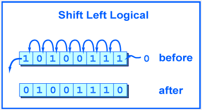
A shift left logical of one position moves each bit to the left by one. The low-order bit (the right-most bit) is replaced by a zero bit and the high-order bit (the left-most bit) is discarded.
Shifting by two positions is the same as performing a one-position shift two times. Shifting by zero positions leaves the pattern unchanged. Shifting an N-bit pattern left by N or more positions changes all of the bits to zero.
The picture shows the operation performed on eight bits. The original pattern is 1010 0111. The resulting pattern is 0100 1110.
The MIPS processor always performs the operation on a 32-bit register and puts the result in a 32-bit register.
sll  d,s,shft      # $d gets the bits in $s
                   # shifted left logical
                   # by shft positions,
                   # where  0 ≤ shft < 32
The ALU (arithmetic/logic unit) which does the operation pays no attention to what the bits mean. If the bits represent an unsigned integer, then a left shift is equivalent to multiplying the integer by two.
Question 2
Here is an 8-bit pattern. Shift it left (logical) by two. Then write the new 8-bit pattern as hex.
| Original | Shift left by two |
|---|---|
0110 1111 | |
0x6F |
Answer
| Original | Shift left by two |
|---|---|
0110 1111 | 1011 1100 |
0x6F | 0xBC |
If the original 8-bit pattern represented an integer, then shifting left by two positions is probably a mistake because a significant bit has been lost.
Shifty program
This program does the shift you just performed in the question. It does it with 32-bit patterns, but for the right-most eight bits the result is the same.
## shiftTwo.asm
##
## Program to logical shift left a pattern
        .text
        .globl  main

main:
        ori      $8, $0, 0x6F       # put bit pattern into register $8
        sll      $9, $8, 2          # shift left logical by two

## End of file
Running the program does the following. Since this time the shift was done with 32 bits, the high order one-bit was not lost.
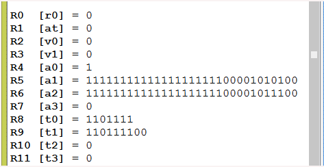
The register display in SPIM has been set to "binary" in the above. High-order zero bits are not shown.
Question 3
Do you think it would be OK to shift the contents of register $8 and put the result back in register $8:
        ori      $8, $0, 0x6F       # put bit pattern into register $8
        sll      $8, $8, 2          # shift left logical by two
Answer
        ori      $8, $0, 0x6F       # put bit pattern register into $8
        sll      $8, $8, 2          # shift left logical by two
Shift in place
When an ALU operation is performed: (1) data is copied from the register(s) into the ALU. Then, (2) the ALU does the operation. Next, (3) the result is written to the designated result register. There is no problem when an operand register is also the result register because the operand data was transferred to the ALU in the first step, leaving the register open to receive the result.
The assembly language statement in the example program is:
sll $9, $8, 2 # shift left logical by two
Here is the machine instruction corresponding to that statement:
   0    0    0    8    4    8    8    0    -- machine instruction in hex

0000 0000 0000 1000 0100 1000 1000 0000    -- machine instruction in bits

000000 00000 01000 01001  00010 000000    -- fields of the instruction

opcode ----- source dest   shft  2ndary    -- meaning of the fields

ALUop          $8    $9     2    sll       -- fields decoded
The sll operation is designated by the 6-bit zero at the beginning of the instruction and the 6-bit zero at the end. The remaining fields give the source register ($8 in this case), the destination register ($9 in this case), and the number of positions to shift (2 in this case). Notice that in the machine language the register designators are reversed from how they occur in the assembly language.
The five zero bits after the opcode are not used. All MIPS instructions are 32 bits. These bits are arbitrarily given the value zero.
Question 4
Study the above machine instruction. Write the machine instruction for shift-left-logical the pattern in $0 by zero positions and leave the result in $0. Here is the instruction in assembly language:
sll $0, $0, 0 # fun machine instruction
Write your machine instruction (as a bit pattern) here:
Hint: on the midterm, I expect you to write the 32-bit pattern for this instruction without hesitation! Memorize it now!
Answer
   0    0    0    0    0    0    0    0    -- machine instruction in hex

0000 0000 0000 0000 0000 0000 0000 0000    -- machine instruction in bits

000000 00000  00000 00000  00000 000000    -- fields of the instruction

opcode -----  $0    $0       0   2ndary    -- meaning of the fields

sll         source  dest  shft   sll
No-op
Register $0 always contains a 32-bit zero (have you heard this before?) so shifting it left by zero positions and attempting to put the result back in $0 does nothing. Any instruction that attempts to alter $0 does nothing, but this instruction is the preferred way of doing nothing.
A machine instruction that does nothing is called (in official computer science jargon) a no-op. The no operation instruction is surprisingly useful, especially for MIPS.
Question 5
What do you call a human who does nothing?
Answer
shiftless
Shift right logical
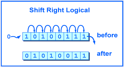
MIPS also has a shift right logical instruction. It moves bits to the right by a number of positions less than 32. The high-order bit gets zeros and the low-order bits are discarded.
If the bit pattern is regarded as an unsigned integer, or a positive two's comp. integer, then a right shift of one bit position performs an integer divide by two. A right shift by N positions performs an integer divide by 2^N.
The "trick" of dividing an integer by shifting should not be used in place of the MIPS arithmetic divide instruction (which will be covered in a few chapters). If you mean "divide" that is what you should write. But the trick is often used in hardware, and sometimes pops up in odd software uses, so you should know about it.
srl  d,s,shft      # $d gets the logical
                   # right shift of $s
                   # by shft positions.
                   # shft is a 5-bit
                   # integer, 0 ≤ shft < 32
Question 6
(Trick Question:) What is the net result if a bit pattern is logical left shifted 2 positions and then logical right shifted 2 positions?
Answer
The two bits on the left of the pattern are guaranteed to be zero; the other bits are not changed.
You might have hastily said that the net result is no change. But if there are one-bits at the left (high order) end of the pattern they will be lost.
OR instruction
MIPS has many instructions that use two registers as operands and that put the result in a register. All the action takes place inside the processor. The data comes from registers, the ALU performs the operation, and the result is written to a register. All this can be done quickly.
The assembly language must specify four things: (1) the operation, (2) the first operand register, (3) the second operand register, and (4) the destination register. Of course, the machine language must encode the same four things in bit patterns.
Here is the OR instruction:
or  d,s,t        # $d gets the bitwise
                 # OR between $s with $t.
Recall that the result of OR is zero only when both operand bits are zero.
Question 7
What is the bitwise OR of the following?

 FEED
 BECA
——————
Answer
FEED      1111 1110 1110 1101
BECA      1011 1110 1100 1010
————      ———— ———— ———— ————
FEEF      1111 1110 1110 1111
When bitwise logic problems are written in hexadecimal, as above, is usually easiest to translate into bits, do the OR, then translate back to hexadecimal.
AND instruction

MIPS has an AND instruction:
and  d,s,t    # $d gets the bitwise
              # AND between $s with $t.
Recall that the result of AND is one only when both operand bits are one.
Question 8
What is the bitwise AND of the following?
 FEED
 BECA
——————
Answer
FEED      1111 1110 1110 1101
BECA      1011 1110 1100 1010
————      ———— ———— ———— ————
BEC8      1011 1110 1100 1000
XOR instruction
You will not be surprised to find that there is a XOR instruction:
xor  d,s,t      # $d gets bitwise XOR
                # between $s with $t.
Recall that the result of XOR is one when only one operand bit is one.
Question 9
What is the bitwise XOR of the following?
 FEED
 BECA
——————
Answer
FEED      1111 1110 1110 1101
BECA      1011 1110 1100 1010
————      ———— ———— ———— ————
4027      0100 0000 0010 0111
NOR instruction
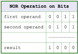
There is a bitwise NOR instruction. There is no immediate operand NOR instruction. NOR is equivalent to performing the OR operation, then complementing the bits (change 0 to 1 and 1 to 0). Here is the assembly language for it:
nor  d,s,t    # $d gets bitwise NOR
              # between $s with $t.
Question 10
What is the bitwise NOR of the following?
 FEED
 BECA
——————
Answer
FEED      1111 1110 1110 1101
BECA      1011 1110 1100 1010
————      ———— ———— ———— ————
0110      0000 0001 0001 0000
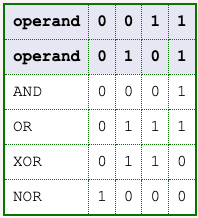
Summary
| AND | OR | XOR | NOR |
|---|---|---|---|
and d,s,t | or d,s,t | xor d,s,t | nor d,s,t |
$d <— $s and $t | $d <— $s or $t | $d <— $s xor $t | $d <— $s nor $t |
The table shows the register with register bitwise logic operations. Register d is the destination (where the result goes); the other two registers s and t contain the operands.
Here is a summary of the operations:
Question 11
Fill in the following:
0 NOR 0 = _____1 NOR 0 = _____NOT 0 = _____NOT 1 = _____
Now answer the question: NOT X = X _____ 0
Answer
0 NOR 0 = 11 NOR 0 = 0NOT 0 = 1NOT 1 = 0
Now answer the question: NOT X = X NOR 0
NOT as NOR with $0

The NOT operation is done by using the NOR instruction with $0 as one of the operands:
nor d,s,$0 # $d <— bitwise NOT of $s.
Question 12
Say that register $8 contains a bit pattern. OR is performed between it and register $0. Register $9 is to be the destination. What is the effect?
or $9,$8,$0
Answer
The bit pattern in $8 is moved to $9 ($8 is unchanged).
or $9,$8,$0 # $9 <— contents of $8.
MOVE as OR with zero
Copying the pattern in a source register to a destination register is called a move operation, even though the source register does not change.
or d,s,$0 # $d <— contents of $s.
Question 13
(Review:) How can a particular bit pattern be loaded into a register?
Answer
With an ori instruction.
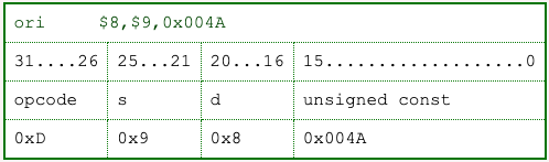
Example program

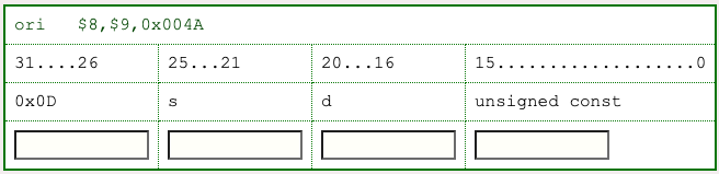
Here are the fields of the ori instruction. The numbers in the first row are bit positions, numbered from the low-order bit on the right. The opcode of the instruction is 0xD. Since the opcode is six bits wide this is understood to stand for 001101. The source register is s, the destination register is d, and the immediate operand is const.
Our example program will assemble the machine code that corresponds to the assembly language instruction:
ori $8,$9,0x004A
The instruction will be assembled in register $25. The program uses bitwise logic and shift operations. Let us say that this example is part of a larger program. To start out, initialize $25 to all zeros (this is called clearing the register).
Question 14
What assembly language instruction clears register $25?
Answer
or $25,$0,$0 # $25 <— $0
(There are others that also work for this).
Target instruction
The program starts with:
or $25,$0,$0 # clear $25
Now the correct bit patterns are placed into the fields of the instruction. The instruction we are assembling is:
ori $8,$9,0x004A
Question 15
Fill in the fourth row with the bit patterns. Use hexadecimal (assume that the bit patterns are truncated on the left to make them the right size).
Answer
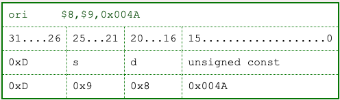
Individual field values
There are four fields in the instruction. We know the bit patterns that go into each field. Let us put those patterns in registers $11, $12, $13, and $14. The program starts out:
| Instruction | Field | Comment |
|---|---|---|
or | $25, $0, $0 | # clear $25 |
ori | $11, $0, ___ | # opcode |
ori | $12, $0, ___ | # operand $s |
ori | $13, $0, ___ | # destination $d |
ori | $14, $0, ___ | # immediate operand |
Question 16
Fill in the fields.
Answer
See below
Shifting the opcode
| Instruction | Field | Comment |
|---|---|---|
or | $25, $0, $0 | # clear $25 |
ori | $11, $0, 0xD | # opcode |
ori | $12, $0, 0x9 | # operand $s |
ori | $13, $0, 0x8 | # destination $d |
ori | $14, $0, 0x004A | # immediate operand |
The ori instruction puts its immediate operand in the low order bits (the right-most bits) of its destination register. So now, with the following code, the registers have the correct patterns but the patterns are not in the correct fields.
or    $25,$0,$0        # clear $25
ori   $11,$0,0xD       # opcode
ori   $12,$0,0x9       # operand $s
ori   $13,$0,0x8       # dest. $d
ori   $14,$0,0x004A    # immediate operand
Register $11 contains the opcode in its right-most bits, like this:

However, the opcode is required to be in the high-order six bits, 26 through 31. A sll will shift the contents of $11 into the correct position.
Question 17
Fill in the amount by which to shift. (Hint: determine which bit should be the new left-most bit. Count the number of bits between its old and new position).
sll $11, $11, _____ # left shift $11 by _____ places
Answer
sll $11,$11,26 # left shift $11 by 26 places
Program so far
Bit position 5 contains the right-most bit of the six-bit opcode. It must be shifted into position 31, and 31-5 = 26.
Here is a run of the program so far. The source code is seen at the right in the window.
Great! Now we have the correct bit pattern placed in the correct 6-bit field. Only one problem: it's in the wrong register. The instruction is supposed to be in register $25.
Question 18
Think of an assembly instruction that will put the opcode into register $25. Here is a start:
or $25, _____ , _____ # move opcode into target register
Answer
or $25,$25,$11 # move opcode into target register
Alternative:
or $25,$11,$0 # move opcode into target register
Source register
Recall the instruction we are trying to assemble: ori $8,$9,0x004A
Now move the bit pattern for the source register $9 into the correct field. Register $12 contains the pattern in its right-most bits, as in the first table below. The pattern should be in bits 25...21 of register $25.

Here, again, is how the assembled instruction will look when it is finished:
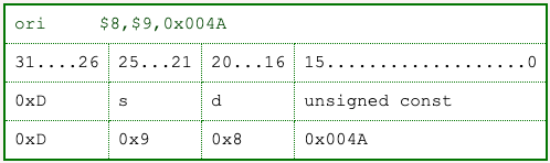
A sll can be used to move this field into position as we did for the opcode. There is a slight problem: the opcode already in $25 must not be erased.
Question 19
Fill in the next part of the program:
sll   $12,$12, _____      # left shift s by _____ places
or    $25, _____ , ______     # move s into target register
Answer
sll   $12,$12,21      # left shift s by 21 places
or    $25,$25,$12     # move s into target register
ORing in a field
The low-order bit of the pattern for $s is in bit position 0 (of register $12). It must be moved to position 21 of the instruction. This is done by shifting left by 21 places. Next, the or copies it into $25, where the instruction being assembled.
The or works like this:
Question 20
Would this instruction have worked as well?
or $25,$0,$12 # move s into target register
Answer
No — the 32-bit result ($0 OR $12) is moved into $25, destroying the opcode already there.
$25 <—— ($0  OR $12)   # wrong
$25 <—— ($25 OR $12)   # right
Destination register and const
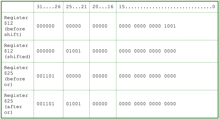
The same method of shifting and oring is used with the bit pattern that designates the destination register. The const part of the instruction is in register $13, and it is in the correct field. It can be copied into $25 using an or instruction. The complete program follows. The comments on each line have been improved. Comments should describe the work done in solving the problem. They should not describe the instruction. Of course, when these notes explain an instruction the comment will often do the same. But that is a poor style, in general.
The following can be copied into the clipboard and pasted into your program editor, then saved to a file and run with SPIM.
## Program to assemble the instruction ori  $8,$9,0x004A
##
        .text
        .globl  main

main:
        or    $25,$0,$0        # clear $25
        ori   $11,$0,0xD       # opcode
        ori   $12,$0,0x9       # operand $s
        ori   $13,$0,0x8       # dest. $d
        ori   $14,$0,0x004A    # immediate operand

        sll   $11,$11,26       # shift opcode into position
        or    $25,$25,$11      # or it into the instruction

        sll   $12,$12,21       # shift operand $s into position
        or    $25,$25,$12      # or it into the instruction

        sll   $13,$13,16       # shift dest $d into position
        or    $25,$25,$13      # or it into the instruction

        or    $25,$25,$14      # or const into the instruction

        ori   $8,$9,0x004A     # The actual assembler
                               # should create the same machine
                               # instruction as we now have in $25

## end of file
Question 21
Would it be possible to dis-assemble the instruction in $25?
Answer
Sure. Bit logic operations can take apart the various fields and put them in different registers.
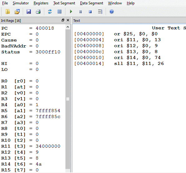
A run of the program
Disassembly sounds like a really great programming assignment. But now let's run the assembler program.
The machine instruction in register $25 is correct, as expected. It would be nice to save the instruction to memory at this point, but you don't know how to do this yet.
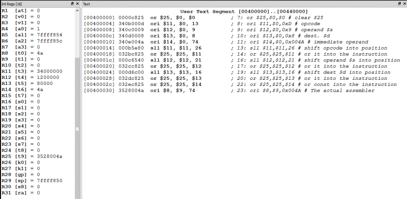
Note that the bit pattern (machine instruction) we assembled in register $25 is the same bit pattern the real assembler gave us for the assembly instruction in the last line of the program.
Question 22
Could this program be written using fewer registers?
Answer
Yes. You only need two. Sounds like another programming exercise.
Chapter quiz
Question 1
Shift left logical the following bit pattern by one position:
0011 1111
- (A)
0111 1110 - (B)
0111 1111 - (C)
0011 1110 - (D)
1011 1111
Answer
A
Question 2
Shift left logical the following bit pattern by two positions:
0011 1111
- (A)
0111 1111 - (B)
1111 1110 - (C)
1111 1100 - (D)
1011 1111
Answer
C
Question 3
Shift right logical the following bit pattern by one position:
0011 1111
- (A)
0000 1111 - (B)
1111 1110 - (C)
0001 1110 - (D)
0001 1111
Answer
D
Question 4
Here is a program that loads register $5 with a bit pattern. Complete the program so that register $4 receives the pattern in register $5 shifted left logical by three positions.
    ori      $5, $0, 0x92AF     # put a bit pattern into register $5
    sll      ___, ___, ___      # shift left logical by three, put
                                # result in register $4
- (A)
sll $5, $3, $4 - (B)
sll 3, $5, $4 - (C)
sll 5, 3, 4 - (D)
sll $4, $5, 3
Answer
D
Question 5
What is the bit-wise OR of the following patterns:
0110 1101
0100 1010
- (A)
0110 1111 - (B)
0111 0110 - (C)
0110 1001 - (D)
1110 0110
Answer
A
Question 6
What is the bit-wise AND of the following patterns:
0110 1101
0100 1010
- (A)
0110 0110 - (B)
0100 1000 - (C)
0110 1001 - (D)
1110 0110
Answer
B
Question 7
What is the bit-wise XOR of the following patterns:
0110 1101
0100 1010
- (A)
0110 0110 - (B)
0010 0111 - (C)
0110 1001 - (D)
1110 0110
Answer
B
Question 8
What is the bit-wise NOR of the following patterns:
0110 1101
0100 1010
- (A)
0110 1111 - (B)
1001 0000 - (C)
1110 1011 - (D)
1110 1110
Answer
B
Question 9
Write the assembly language statement that will reverse the values of each bit in register $5 and put the result in register $8.
- (A)
nori $8,$5,$0 - (B)
nor $8,$5,$0 - (C)
xor $8,$5,$0 - (D)
nor $5,$8,$0
Answer
B
Question 10
Write the assembly language instruction that copies the bit pattern in register $13 to register $15.
- (A)
ori $15,$13,$0 - (B)
andi $13,$15,$15 - (C)
and $13,$15,$15 - (D)
or $15,$13,$0
Answer
D
Programming exercises
For these programming exercises, use only those instructions that have been discussed so far in these notes:
andandinorororisllsrlxorxori
In the Settings menu of SPIM
- set Bare Machine ON
- Allow Pseudo Instructions OFF
- Load Trap File OFF
- Delayed Branches ON
- Delayed Loads ON
- Mapped IO OFF
- Quiet OFF
Run the programs by setting the value of the PC to 0x400000 and then single stepping (pushing F10) or by multiple stepping (push F11 and enter a number of steps). Observing the results in the SPIM window.
Exercise 1 (*)
Put the following bit pattern into register $1:
DEADBEEF
A. Easy program: do this using just three instructions.
B. Somewhat harder: do this one letter at a time, using ori to load each letter (each nibble) into a register, then shifting it into position. You will need to use ori, or, and sll instructions. Look at the contents of register $1 as you push F10 to single step the program.
Exercise 2 (*)
In each register $1 through $7 set the corresponding bit. That is, in register 1 set bit 1 (and clear the rest to zero), in $2 set bit 2 (and clear the rest to zero), and so on. Use only one ori instruction in your program, to set the bit in register $1.
ori $1,$0,0x01
Don't use any ori instructions other than that one. Note: bit 1 of a register is the second from the right, the one that (in unsigned binary) corresponds to the first power of two.
Exercise 3 (*)
Start out a program with the instruction that puts a single one-bit into register one:
ori $1,$0,0x01
Now, by using only shift instructions and register to register logic instructions, put the pattern 0xFFFFFFFF into register $1. Don't use another ori after the first. You will need to use more registers than $1. See how few instructions you can do this in. My program has 11 instructions.
Exercise 4 (*)
Put the bit pattern 0x55555555 in register $1. (Do this with three instructions.)
Now shift the pattern left one position into register $2 (leave $1 unchanged).
Put the the bit-wise OR of $1 and $2 into register $3. Put the the bit-wise AND of $1 and $2 into register $4. Put the the bit-wise XOR of $1 and $2 into register $5.
Examine the results.
Exercise 5 (**)
Put the bit pattern 0x0000FACE into register $1. This is just an example pattern; assume that $1 can start out with any pattern at all in the low 16 bits (but assume that the high 16 bits are all zero).
Now, using only register-to-register logic and shift instructions, rearrange the bit pattern so that register $2 gets the bit pattern 0x0000CAFE.
Write this program so that after the low 16 bits of $1 have been set up with any bit pattern, no matter what bit pattern it is, the nibbles in $2 are the same rearrangement of the nibbles of $1 shown with the example pattern. For example, if $1 starts out with 0x00003210 it will end up with the pattern 0x00001230.
A. Moderately Easy program: do this using ori instructions to create masks, then use and and or instructions to mask in and mask out the various nibbles. You will also need rotate instructions.
B. Somewhat Harder program: Use only and, or, and rotate instructions.
Exercise 6 (***)
Start out register $1 with any 32-bit pattern, such as 0x76543210. Now, put the reverse of that pattern into register $2, for the example, 0x01234567.