Programmed Introduction to MIPS Assembly Language
Pretty much everything in this programmed introduction to the MIPS assembly language comes directly or indirectly from Central Connecticut State University's eponymous course webpage.
The index page for the original course site may still be quite useful.
Another course on Java from the same author may be of future use as well.
This is a course in assembly language programming of the MIPS processor. It emphasizes the topics needed for study of computer architecture: bits, bit patterns, operations on bit patterns, and how bit patterns represent instructions and data. This course is equivalent to a semester-long junior college or university course (except, perhaps, for the emphasis on bit patterns).
The emphasis of the course is on understanding how computers work. This will provide a basis for further study of computer architecture and computer software. The MIPS processor, the subject of this course, has a well designed architecture and is particularly fruitful to study. However, the goal of the course is not to turn you into a MIPS programmer, but to give you an understanding of all computer systems.
The only equipment you need for this course is a PC. The only software you need is the SPIM simulator of the MIPS32 processor and a text editor. The simulator is available by free download (see appendix A). Example programs are presented using an MS Windows operating system. However, you can use any platform that runs SPIM. (There are many.)
Assembly Language is normally taken the semester after a course in a high level programming language (such as Java or C). This course assumes that you have this background although no specific programming language is required.
Read the pages of this course actively. Think about and answer the question at the bottom of each page. (This style of tutorial is called programmed learning. It is very effective for technical material.) Most questions call for just a little thought. Some call for pencil and paper. Keep a pencil and a scrap of paper next to your keyboard. Each chapter is about 15 pages long. Spend several minutes per page. You can read each chapter in about 30 minutes. However, for maximum benefit, you should run some of the example programs, write some programs of your own, and then think about your results. This may take several hours.
Course outline
- Part 1: Prelude to Assembly Language: Assembly language: what it is, why it is studied, and where it is used.
- Part 2: Data Representation: Data: characters and integers. The binary addition algorithm.
- Part 3: Running SPIM; Bitwise Logic: Running SPIM. MIPS programming. Bitwise logic operations.
- Part 4: Integer Arithmetic and Memory Access: Integer arithmetic. Moving data to and from memory.
- Part 5: Branches, Decisions, and Loops: Program flow: branch, jump, and set instructions; loops, and decisions.
- Part 6: Extended Assembly Language: The assembler extends bare machine language. Registers have mnemonic names. Pseudoinstructions extend the bare hardware.
- Part 7: The Stack and Subroutine Linkage: Programs are divided into sections called subroutines. At run time, the stack is used to save and to restore a subroutine's values.
- Part 8: Floating Point Data: Bit patterns are used to represent floating point numbers. More machine instructions are used to do floating point arithmetic.
- Part 9: Data Structures in Assembly Language:
Appendix A — Downloading and Installing SPIM.
This on-line course uses SPIM. SPIM is a simulator for the MIPS32 processor instruction set architecture (ISA). All you need for this course is SPIM and a text editor. The latest version of SPIM, called QtSpim, is available for free.
You will need a text editor. The text editor that comes with Microsoft operating systems, Notepad, will work, but just barely. A better text editor is much more convenient. If you are already using a text editor that came with a programming environment it will work fine. Sometimes these editors are called "program editors." The editor that comes with Visual Basic will not work. A "word processor" such as Word or WordPad will not work well, either.
One good text editor is Visual Studi Code, which can be downloaed for free.
If you are familiar with downloading and installing programs, download and install SPIM and skip the rest of this appendix. If (as happens all too often) SPIM has moved to a new location, look for it with a search engine. It is used by many schools and is downloadable from several locations.
SPIM is a MIPS32 simulator originally written by James R. Larus to support a course in compiler design at the University of Wisconsin-Madison. It has been improved and expanded and now exists in several versions. The downloads page contains versions for every operating system. You can choose the one that works on your computer.
- Point your Web browser to Source Forge.
- Click "Download Spim"
- There are several files that can be downloaded.
- Download the most recent version that can be run on your computer.
Appendix B — Register Use Chart
| Register Number | Mnemonic Name | Conventional Use | Register Number | Mnemonic Name | Conventional Use | |
|---|---|---|---|---|---|---|
$0 | $zero | Permanently 0 | $24, $25 | $t8, $t9 | Temporary | |
$1 | $at | Assembler Temporary | $26, $27 | $k0, $k1 | Kernel | |
$2, $3 | $v0, $v1 | Value returned by a subroutine | $28 | $gp | Global Pointer | |
$4-$7 | $a0-$a3 | Subroutine Arguments | $29 | $sp | Stack Pointer | |
$8-$15 | $t0-$t7 | Temporary | $30 | $fp | Frame Pointer | |
$16-$23 | $s0-$s7 | Saved registers | $31 | $ra | Return Address |
There are also 32 floating point registers $f0 – $f31.
Appendix C — MIPS Assembly Instructions
| Instruction | Operands | Description |
|---|---|---|
add | d,s,t | |
addu | d,s,t | |
addi | d,s,const | |
addiu | d,s,const | |
and | d,s,t | |
andi | d,s,const | |
beq | s,t,addr | |
bgez | s,addr | |
bltz | s,addr | |
bne | s,t,addr | |
div | s,t | |
divu | s,t | |
j | target | |
lb | d,off(b) | |
lbu | d,off(b) | |
lh | d,off(b) | |
lhu | d,off(b) | |
lui | d,const | |
lw | d,off(b) | |
mfhi | d | |
mflo | d | |
mult | s,t | |
multu | s,t | |
nor | d,s,$0 | |
nor | d,s,t | |
or | d,s,$0 | |
or | d,s,t | |
ori | d,$0,const | |
ori | d,s,const | |
sb | d,off(b) | |
sh | d,off(b) | |
sll | $0,$0,0 | |
sll | d,s,shft | |
slt | d,s,t | |
slti | d,s,imm | |
sltiu | d,s,imm | |
sltu | d,s,t | |
sra | d,s,shft | |
srl | d,s,shft | |
sub | d,s,t | |
subu | d,s,t | |
sw | d,off(b) | |
xor | d,s,t | |
xori | d,s,const | |
Appendix D — Binary Addition Calculator (Applet)
The binary addition algorithm operates on two bit patterns and results in a bit pattern. Usually all three patterns are the same size, and all three represent unsigned integers or all three represent signed integers.
Addition of one-bit binary operands is easy:
       0    0    1    1
      +0   +1   +0   +1
     ---  ---  ---  ---
      00   01   01   10
These sums show one-bit operands and two-bit results. For multi-bit operands, the above sums are used for each column. The left-most bit of the one-bit result is used for the carry into the next column. For example, here is the sum of two four-bit integers:
     0 1 1 0      <--  the carry into each column
       0 1 1 0    <--  first operand
       0 1 1 1    <--  second operand
       -------
       1 1 0 1    <--  the result
Adding the bits in one column produces a carry bit that is placed at the top of the next column to the left. This is called the carry out for this column and the carry in for next column left. Every column but the right-most includes a carry bit that comes from the column to its right. (Think of the right-most column as having a carry-in of zero.) Now columns have three bits to be added, and the addition rules must be extended:
       0    0    0    0    1    1    1    1
       0    0    1    1    0    0    1    1
      +0   +1   +0   +1   +0   +1   +0   +1
     ---  ---  ---  ---  ---  ---  ---  ---
      00   01   01   10   01   10   10   11
Of course, you don't have to memorize these rules. Just count the number of 1's in each column and write that count in binary.
Computers (usually) add two N-bit integers together to produce an N-bit result and a carry-out of the left-most column. Every bit of the result must have a value. The following shows an 8-bit addition:
        0 0 0 0 1 1 0 0
          0 0 0 0 1 1 1 0
          0 0 0 0 0 1 0 1
          ---------------
          0 0 0 1 0 0 1 1
The result is an N-bit pattern and a carry bit. The carry out from the left-most column might be zero or one. Each input pattern can be any pattern at all, and the algorithm will always produce an output pattern. However if the inputs are regarded as positive integers, some output patterns don't correspond to a correct sum. This is called overflow. Computer hardware looks at the carry into and out of the left-most column to determine if overflow happened.
Here is an implementation of this algorithm for 8-bit operands. Click on the bits of the operands X and Y to toggle the bits from 0 to 1 and back.
Appendix E — ASCII Chart
This chart shows the bit patterns that encode various characters using the ASCII encoding scheme. Each character is encoded as an 8-bit pattern. The chart shows the pattern using the hexadecimal name for the pattern. The column heading gives the 1's place digit of the hex and the row heading gives the 16's place digit of the hex. For example, find the character 'K' in the central (yellow) portion of the chart. The column heading is B and the row heading is 4 so the bit pattern is 0x4B, or 0100 1011.
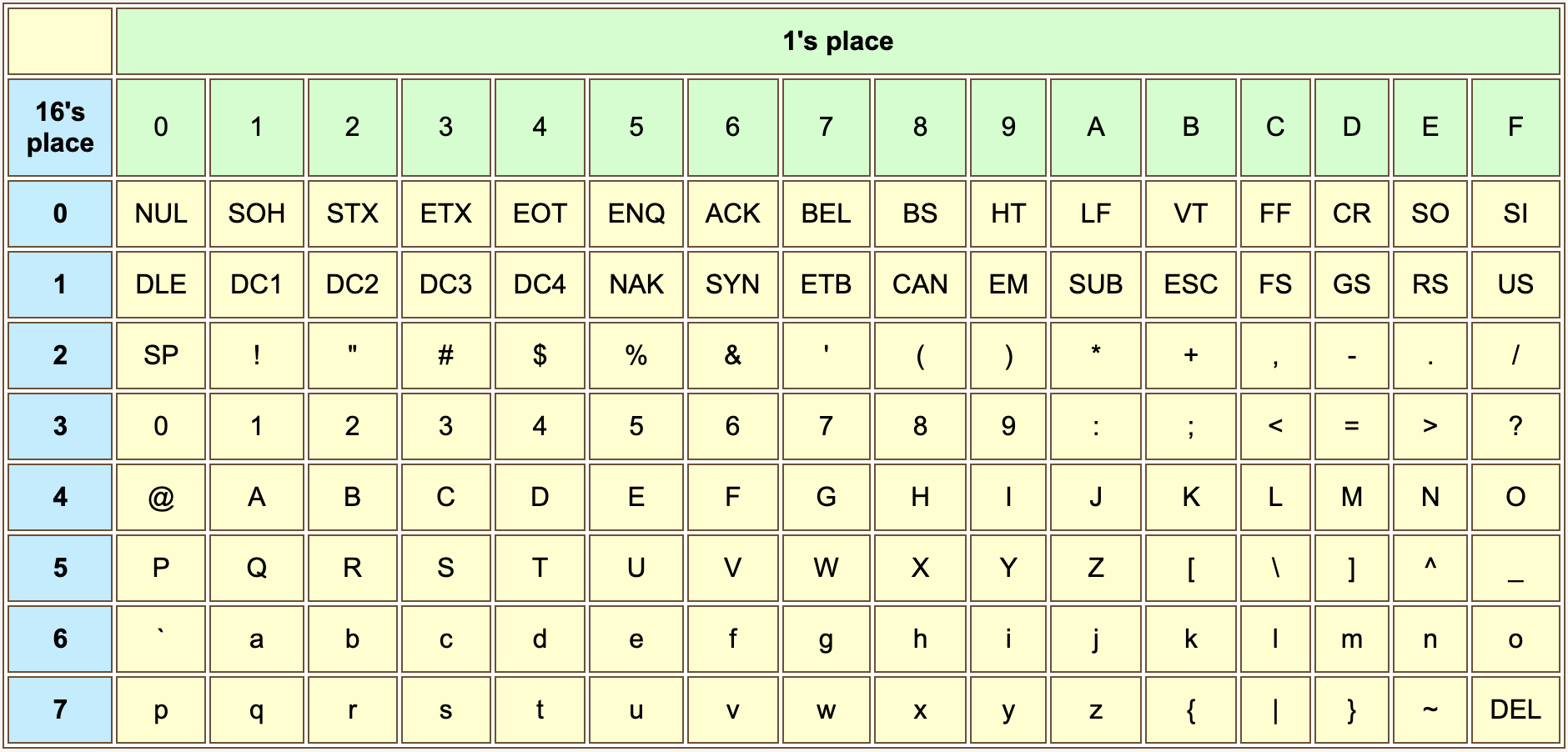
The ASCII code for CR is 0x0D. The ASCII code for character 'A' is 0x41.
Control characters are abbreviated in capital letters. Some useful ones are:
- BS (backspace)
- HT (horizontal tab)
- LF (line feed)
- VT (vertical tab)
- FF (formfeed)
- CR (carriage return)
- ESC (escape)
- SP (space)
Actually, space is a printable character, not a control character. Various things of ASCII-interest are available at Jim Price's ASCII page.
Appendix F — SPIM Exception Handler Services
| Service | Code in $v0 | Arguments | Returned Value |
|---|---|---|---|
| print integer | 1 | $a0 == integer | |
| print float | 2 | $f12 == float | |
| print double | 3 | $f12 == double | |
| print string | 4 | $a0 == address of string | |
| read integer | 5 | $v0 <-- integer | |
| read float | 6 | $f0 <-- float | |
| read double | 7 | $f0 <-- double | |
| read string | 8 | $a0 == buffer address; $a1 == buffer length | |
| allocate memory | 9 | $a0 == number of bytes | $v0 <-- address |
| exit | 10 |